
Regenerative Frequency Divider
This test project started as a study of the work from Matjaz Vidmar, published at the Microwave Journal in 1999, the original publication can be read here.
As stated by Matjaz, today's frequency division is largely done by digital semiconductor logic. Even so, analog regenerative dividers can be useful for high microwave or mmWave frequencies, although only narrowband operation is possible.
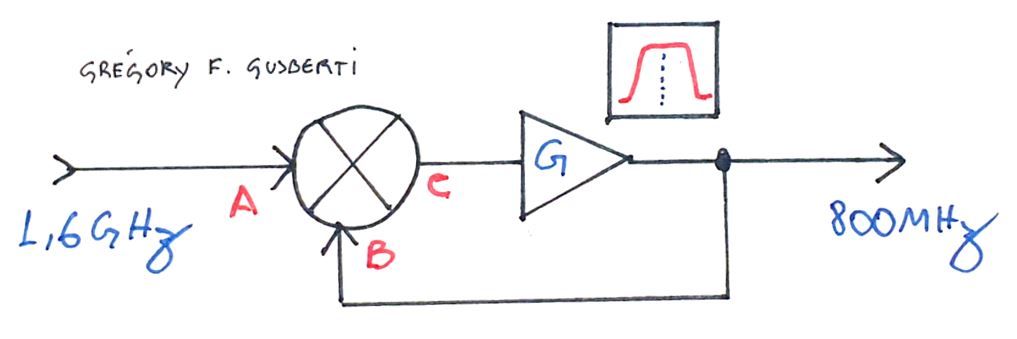
The concept is easily understood looking at the simplified block diagram of the frequency divider. The input signal is applied to the mixer input A. The mixer's output C is amplified by a narrowband amplifier and fed back to the other mixer input.
The mixer will output the sum and difference tones of the A and B inputs. Positive feedback around the amplifier is possible exactly when the B input has half the frequency of the A input. If the amplifier gain is enough to overcome the mixer insertion loss, spontaneous oscillation will be sustained at half the input frequency.
In his original article, Matjaz explains the working principle by the phase conjugation operation, even being a mathematical complete explanation, I suggest the reader to think about it in a more practical way.
To decrease the output phase noise and increase isolation from the input signal, the amplifier is made bandpass, presenting a narrow operational band around the half frequency output, increasing the gain margin of not desired frequencies.
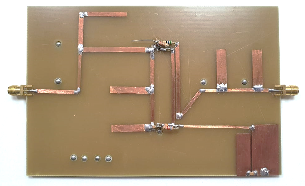
The prototype was assembled using microwave prototyping techniques. Transmission lines are made using copper tape over a single sided FR4 PCB. I explained this kind of construction in more detail in the article about Frequency Multiplier with PIN diode.
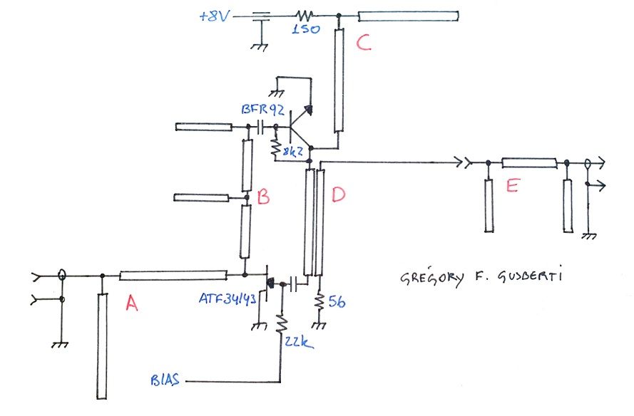
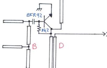
A and B form a diplexer network that routes the correct signal frequencies for proper operation. Starting from the input, the A network is responsible for isolating the half frequency output from leaking through the input port. The B network works isolating the BFR92A amplifier from the input signal, as its main goal is to only amply the desired output frequency.
The AT34143 is a pseudomorphic HMET transistor, acting as a balanced passive mixer. Mixing action happens by impedance modulation, as the channel conductance is modulated by the signal swing at the gate. As the transistor is not used in the active region, balanced operation happens, because zero gate to drain transconductance guarantee zero amplification of the applied gate signal thus increasing port isolation (port B to C).
The half frequency tone reaches the amplifier at the end of the B network, with the amplification compensating for the conversion loss of the passive mixer. The narrowband C network bias the amplifier with the peaking frequency at the desired output, this further increases the rejection of the input frequency.
Part of the amplifier output is coupled to the output connector using a backward 20dB quarter-wave coupler, the D network. The coupler directivity helps to isolate any mismatch from the output, that would reduce the divider performance, as any reflected wave will be mixed in the HMET transistor. The output of the system is very clean, with the original input tone at -25dBc.
To improve the output spectrum even more, I followed the coupler with a stub notch filter, the network E, effective reducing the input frequency leakage to less than -42dBc.
Passive Mixer Bias
The mixer operation, conversion loss and compression is highly dependent on the gate bias, so I supplied the bias voltage using a separated power supply. After proper operation is reached, the gate can be biased using a divider resistor from the 8V supply.
If not operated at the correct drain conductance region, positive feedback action will happen by harmonic and intermodulation products that also generate phase conjugation. This will be seen as a mess at the output spectrum, corrupting the frequency divider operation, making the system useless.
Operation
Operation was confirmed by applying a microwave 1,6GHz signal at the input connector. A power of 0dBm happened to be the one providing better startup of the positive feedback loop. Higher power easily corrupt the passive mixer operation, probably by signal compression. If lower input signals are desired, an input amplifier, also using a BFR92A could easily be added to the design.
The output is a clean 800MHz signal. The spectrum is also quite clean, owning to the narrowband design and the E network.
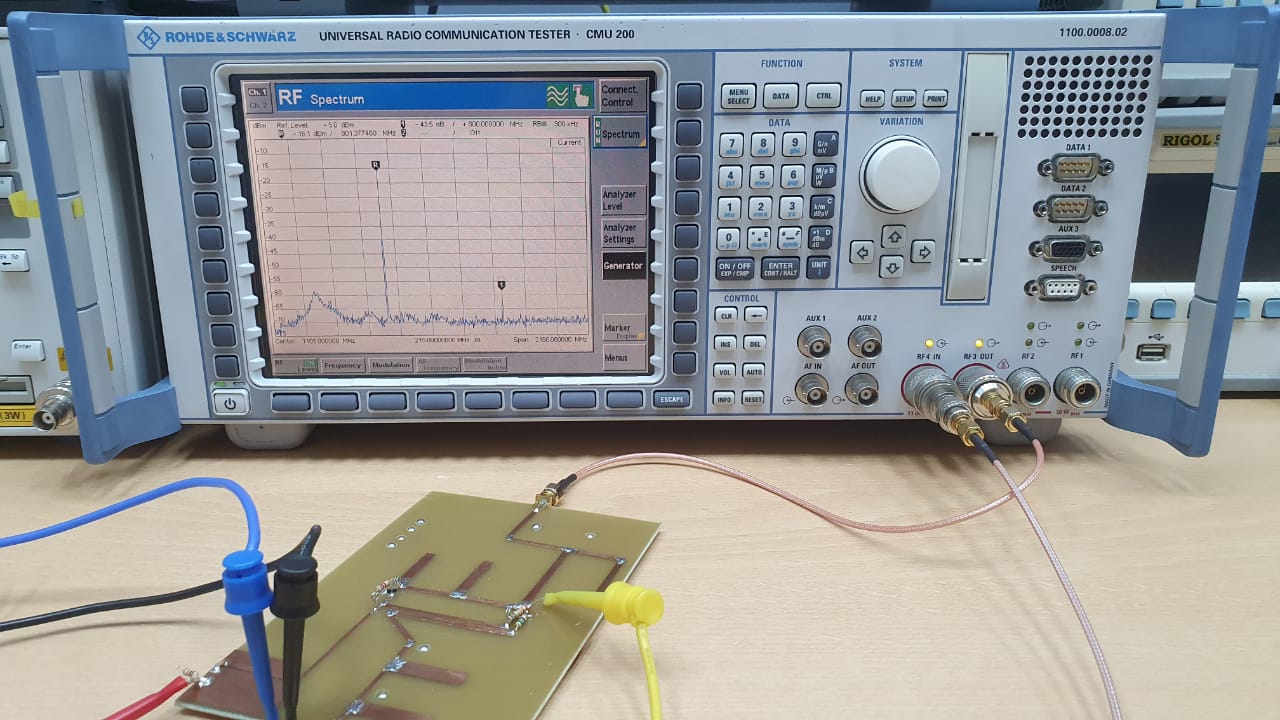
It is possible to see a bump of energy in the spectrum, near 160MHz. I believe the BFR92A has very high gain, and this contributes to a tendency of oscillation in lower frequencies. Care needs to be taken to understand if this behavior can lead to interference or phase noise degradation of the main output tone.
In a revision of the design, I would consider an improvement on the C network to reduce the positive feedback around these VHF bands.