
HP 1152A Mod
Active probes are a must when designing high frequency topologies. This article covers a modification procedure to adapt HP 1152A active probes into modern oscilloscopes.
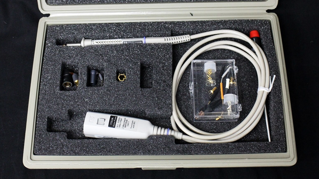
The HP1152A is a 2.5 GHz active probe, with 100 kΩ @ 0.6 pF input impedance. This old design utilizes an old version of the HP AutoProbe interface, where probe detection and recognition is accomplished sensing analog resistors through the 9 pin interface.
Modern Agilent and Keysight oscilloscopes utilizes the AutoProbe system with the addition of digital Probe ID, using an I2C memory to indicate the probe model, serial number and calibration parameters. The memory is an industry standard 24C02 and the scope reads all 256 bytes when the probe is connected.
In the HP 1152A, one resistor (at pin 5) indicates the model of the probe, using the old analog Probe ID way, and a second resistor (at pin 7) configures the oscilloscope for supplying 4V to the probe (through pin 1).
Modern active probes don't utilize the configurable supply, so new oscilloscopes are capable of delivering only 5V, like in the case of the DSO-X 3000 utilized here. If the old probe is attached to the modern oscilloscope, it shows a dialog indicating that an unsupported probe was connected.
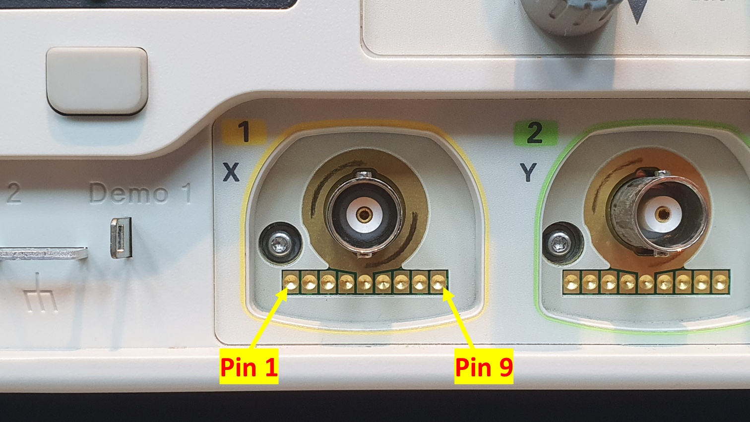
The AutoProbe interface pinout is:
- +3V to +6V (configurable by resistor at pin 7)
- -3V to -6V (configurable by resistor at pin 7)
- N/A
- Digital Probe ID I2C SDA.
- Analog Probe ID (46k6 resistor to GND means modern digital Probe ID).
- Digital Probe ID I2C SCL.
- Voltage configuration resistor (10k to GND means 5V).
- -12V.
- +12V (needed to read the modern 1156A probe).
For utilizing the HP 1152A with the modern DSO-X scope, four main modifications are needed:
- Installation of a 4V LDO to supply the probe from the scope 5V supply.
- Installation of a 24C02 memory, with the content copied from a modern probe.
- Replacement of the analog Probe ID resistor (pin 5) for a 46k6 resistor (indicating digital Probe ID).
- Replacement of the voltage supply resistor (pin 7) for 10k (indicating that the probe supports 5V).
Luckily, I have a modern Agilent 1156A probe, for copying the memory.
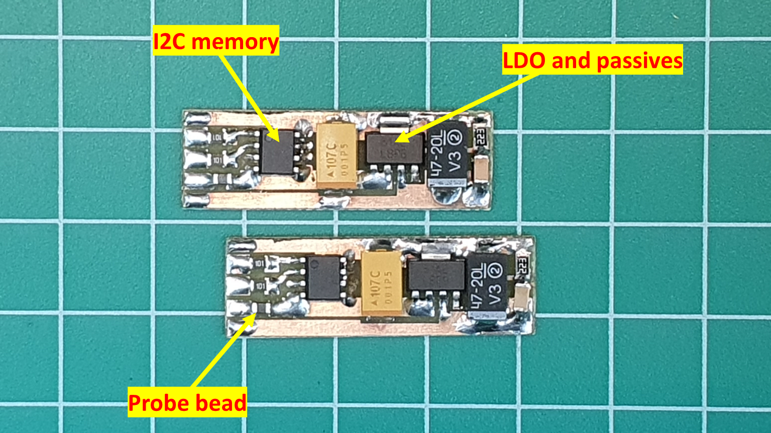
Two mod PCBs were designed, containing a LDO regulator and the I2C memory. The utilized regulator is overkill, but it was readily available. The PCB is small enough to fit in the original enclosure, with the probe's main PCB.
The memory is hard-wired to address 0xA2 (0x51) (depends on how you read), and the SCL and SDA pins are protected by 100 Ohm resistors, as it will be exposed in the AutoProbe connector. All other components are related to the LDO, an LP3964 regulator, setting the 4V output and needed capacitances.
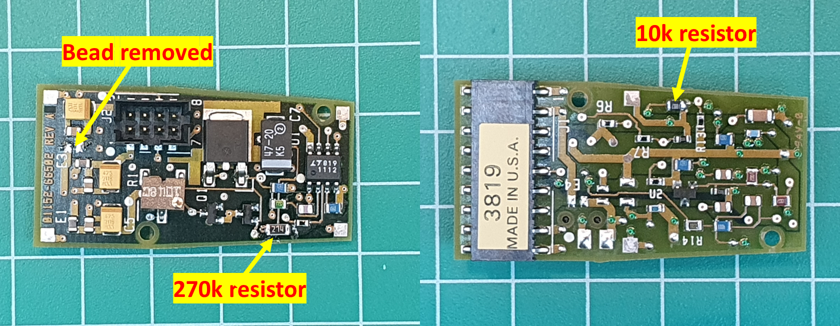
As the HP 1152A identifies itself - using the analog Probe ID mode - using a 56k resistor, and the value needed to indicate a digital Probe ID is 46k6, the addition of a 27ok resistor in parallel proved to work, generating a combined resistance of ~46k3.
The voltage setting resistor, that needs to present 10k, was replaced by a new resistor.
The original 4V line trace was opened, by desoldering an SMD bead. This bead was reutilized in the mod PCBs, filtering the 5V input.
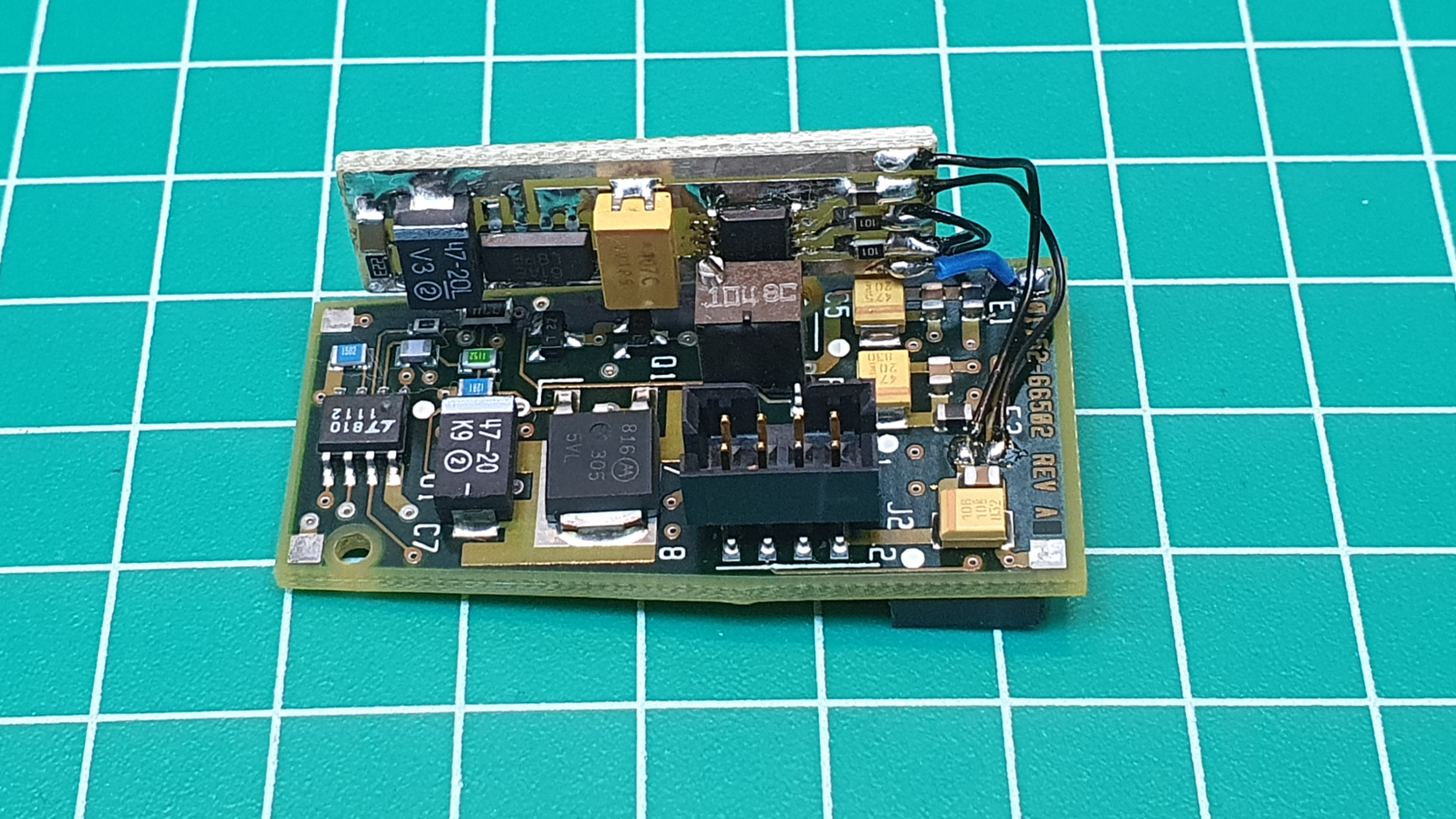
The mod PCBs were installed into the main PCBs. SDA and SCL lines connect directly to pin 4 and pin 6. The 5V in (from the pin 1) and 4V out (to the main PCB) were connected to the exposed pads of the removed beads, facilitating the series connection of the LDO regulator.
The GND was connected using a thicker wire, to a ground pad available on the main PCB, also working as mechanical support. After installation, the mod PCB was protected using shrink tube.
For reading and writing to the memories, a simple Arduino setup was assembled.
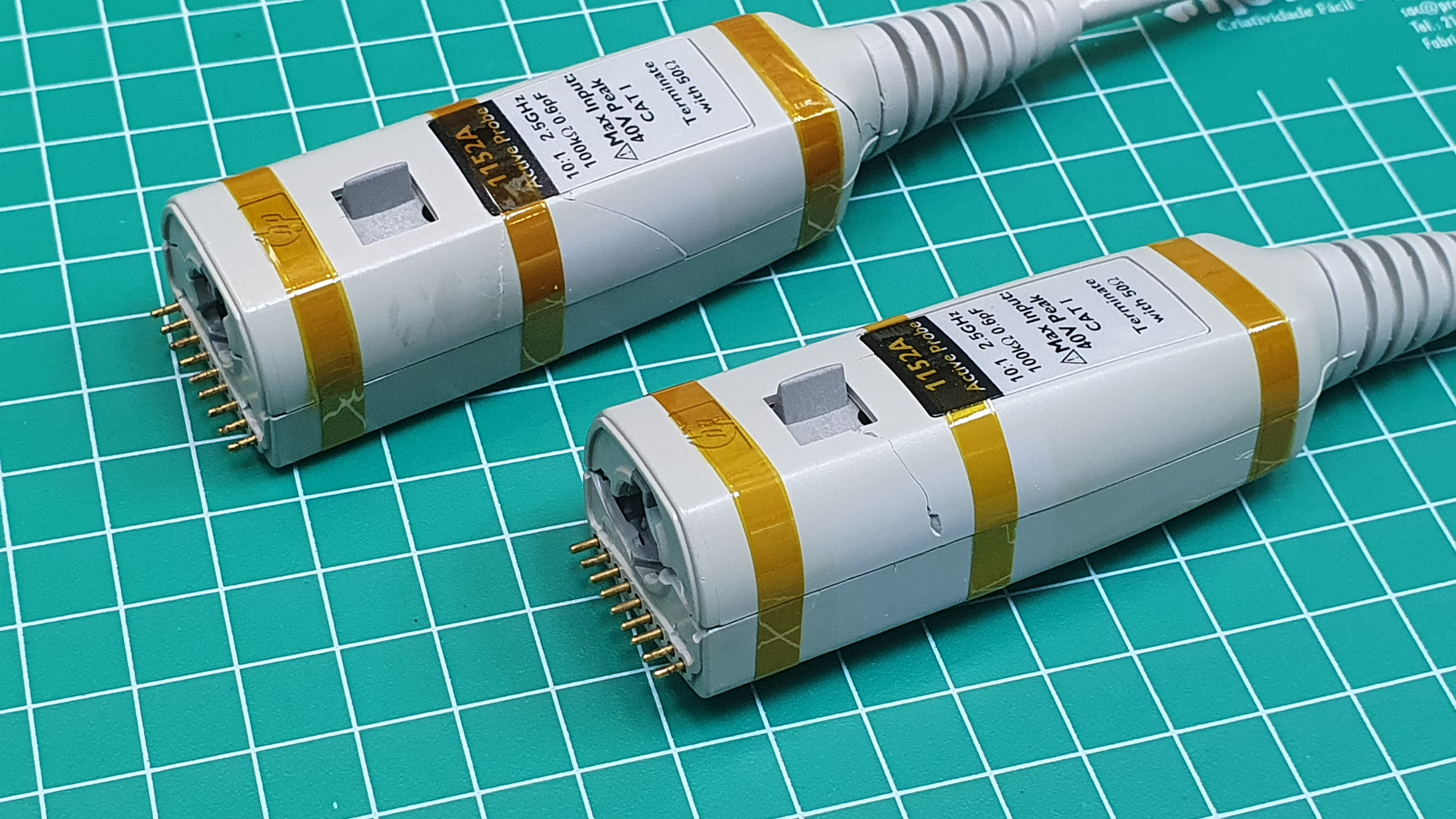
Plastics from the probe connector case were very brittle, probably caused by storage in harsh conditions (high temperature / high UV). The cases were in pieces after the handling through the modification.
With a lot of care, the probes were reassembled, with the case secured by Kapton tape. If you have burned probes, I may be interested to buy them for getting the enclosures, send me a note!