
Varactor tuned filter
Adjustable filters are desirable when the amplitude or phase of a signal needs to be changed dynamically, using a controlling voltage or current. This article demonstrates a simple design, tested for use as a cheap phase-shifter for a phased-array application.
As shown in the article about LCR jig for measurement of varactors, slow rectifier diodes perform like varactors when reverse biased, and are a cheap alternative working up to the start of the UHF band.
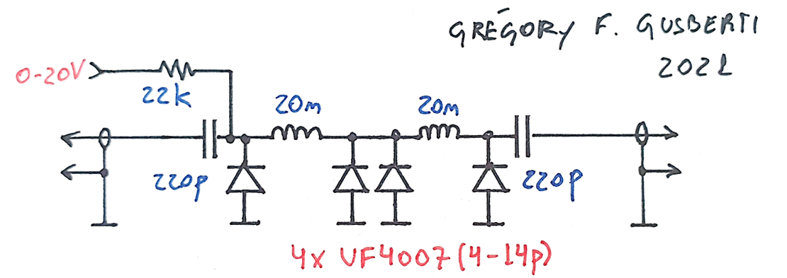
The design consists of two half-wave sections, where the capacitors are replaced entirely by the diodes. The UF4007 was chosen for the 4pF t0 14pF range, accommodating the correct reactances for the 50ohm filter near 433MHz. The two 220pF capacitors couple the RF signal and isolates the DC controlling voltage.
The filter was assembled as a prototype for a phased-array system, where the phase of five dipole antennas needs to be controlled individually. The half-wave behavior of the design allows the phase to be adjusted, but with the negative consequence of variations of insertion-loss (because the amplitude response changes accordingly).
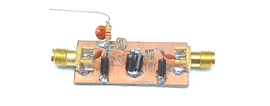
The inductors are placed purposefully not aligned, minimizing the interaction from near coupling.
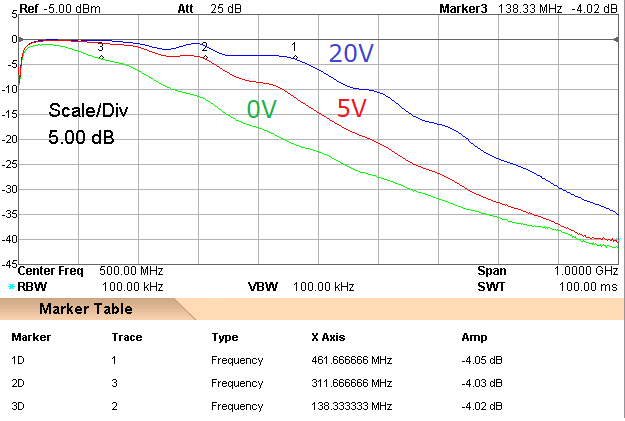
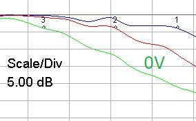
At the maximum control voltage of 20V, the filter presents the higher bandwidth of 460MHz. The range of adjust for the -3dB cut-off point is higher than 300MHz, allowing a pass-band of 138MHz with 0V.
An ideal tuned half-wave filter would necessarily need adjustable inductors, to keep the filter impedance constant at 50ohm. Nevertheless, for smaller ranges of adjust, where variations of impedance are smaller, the simplicity of the topology justifies itself.
The pass-band insertion loss decreases with higher control voltages, where the diodes behave as smaller capacitors, thus presenting a higher Q factor. This happens because the diode small-signal series resistance is virtually unchanged for changes in reverse voltages.
A deeper investigation is needed if overall non-linearity and distortion is a concern. The fundamental non-linear behavior of the diode capacitance will largely distort the signal at higher RF powers, lowering the IIP3. The frequency response plots were captured with -10dBm, probably just at the limit of usable power levels.