JIG for LCR - Zener and Varicap capacitance measurement

Sometimes when designing low frequency VCOs for HF and VHF bands we need high capacitance varicaps, to accomplish the desired frequency and sweep ratio. It is well-known that some rectifier and zener diodes act as general purpose varicaps, as the depletion capacitance is modulated by some applied DC voltage.
To measure a diode capacitance using a conventional LCR I designed a JIG to decouple that AC capacitance measure from the DC voltage. With this approach capacitance vs. voltage curves become easy to take.
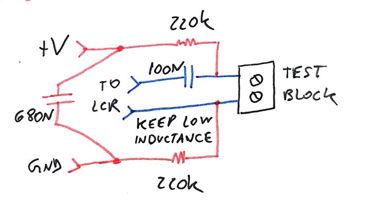
The blue parts are the path for the AC LCR signal. It is basically a 100N coupling capacitor that blocks the DC voltage, allowing the LCR to see only the junction AC response.
Now we couple the DC voltage using the red parts. Two 220K resistors bias de junction without disturbing the AC measurement. I also added a capacitor to prevent any interfering signal from the DC supply from reaching the LCT meter.
It's really important to keep the inductance of the blue connections low, as it will appear to the LCR as series positive reactance. Even if your LCR meter has a zero function, keep it low.
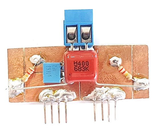
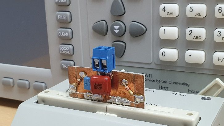
You can see the construction of the JIG here. I used a screw terminal block for quick change of the diode on test. Inductance is minimized by the large copper areas on the PCB, leading to the pin connectors at the bottom, that can be directly connected in the LCT test stand.
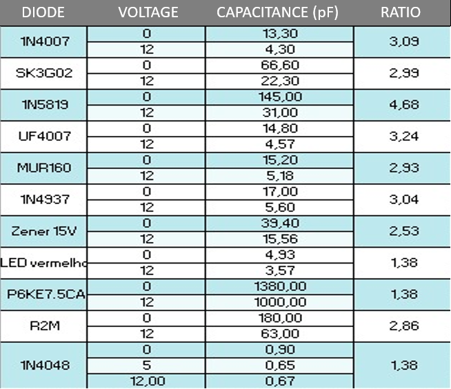
I got a bunch of jellybean diodes, zeners and rectifiers, and tested them all. The junction capacitance for different bias voltages can be seen in the table below. My preferred choice for HF and VHF oscillators is the 1N5819, giving a wide capacitance ratio.