
Blocking Oscillator
Blocking Oscillators were the standard method for creating oscillators and pulses in the Vacuum Tube era. Fast rising/fall times with long pulse repetitions came from a positive feedback topology and from a complex interaction between the pulse-transformer, the grid capacitor, grid resistor and the characteristics of the tube.
The active device, being a triode or a pentode tube, works in small-signal and in large-signal for different parts of the oscillation cycle. The "blocking" nomenclature is named from the fact that for a long period of the cycle, the tube is kept with a high negative voltage on its grid, reducing plate current to zero a.k.a. blocking the conduction.
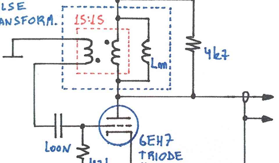
The prototype circuit uses a common variable-mu 6EH7 pentode tube, connected as a triode (screen connected to plate and suppressor to ground). Positive feedback is accomplished by the pulse-transformer, transferring energy from the plate to the grid of the tube.
Bias of the plate is set by the 60V supply, and the 4k7 plate resistor helps damp resonances of the transformer parallel capacitance.
The pulse transformer is represented by its ideal behavior - the 15:15 turns ratio ideal-transformer (red box) that reflects the secondary impedance to the plate side - and by the magnetizing inductance Lm. This inductive reactance at the primary side models the energy storing in the transformer core.
Excitations at the grid are amplified by the tube and transferred to the plate as a signal change in the opposite direction, as the topology present negative gain - a positive grid perturbation appears at the plate as a negative going signal.
As the transformer connection to the grid is inverted (note the dots), any negative going signal at the plate is fed back to the grid in a positive direction, contributing even more to signal change. This is the positive feedback behavior that enhances rise/fall times and switches the tube state between conduction and blocking in a fast way.
The 100nF grid capacitor and 47k grid resistor form an RC network that mostly controls the blocking period (cut-off of the tube). Stored energy on the capacitor biases the tube negatively, ceasing the conduction of current. This off period is proportional to the RC constant.
For this prototype, the pulse transformer uses a 1:1 ratio of 15 turns of bifilar windings on a Ferrite toroidal core. Bifilar winding reduces leakage inductance, increasing the bandwidth, thus providing very fast rising/fall times in conjunction with the positive feedback.
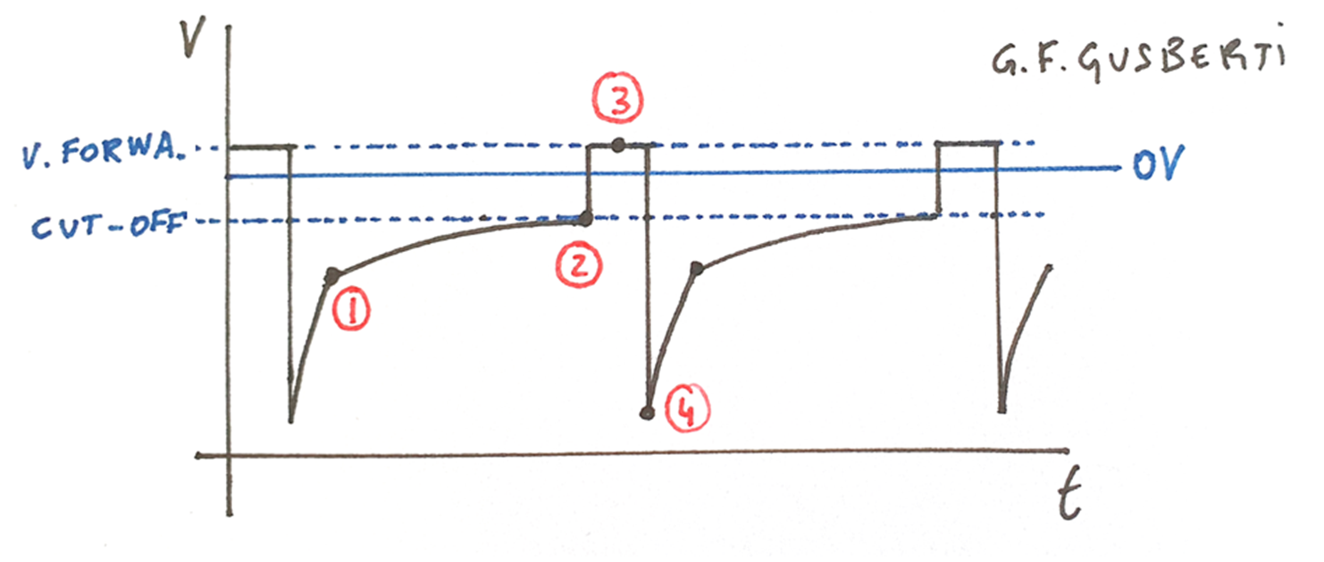
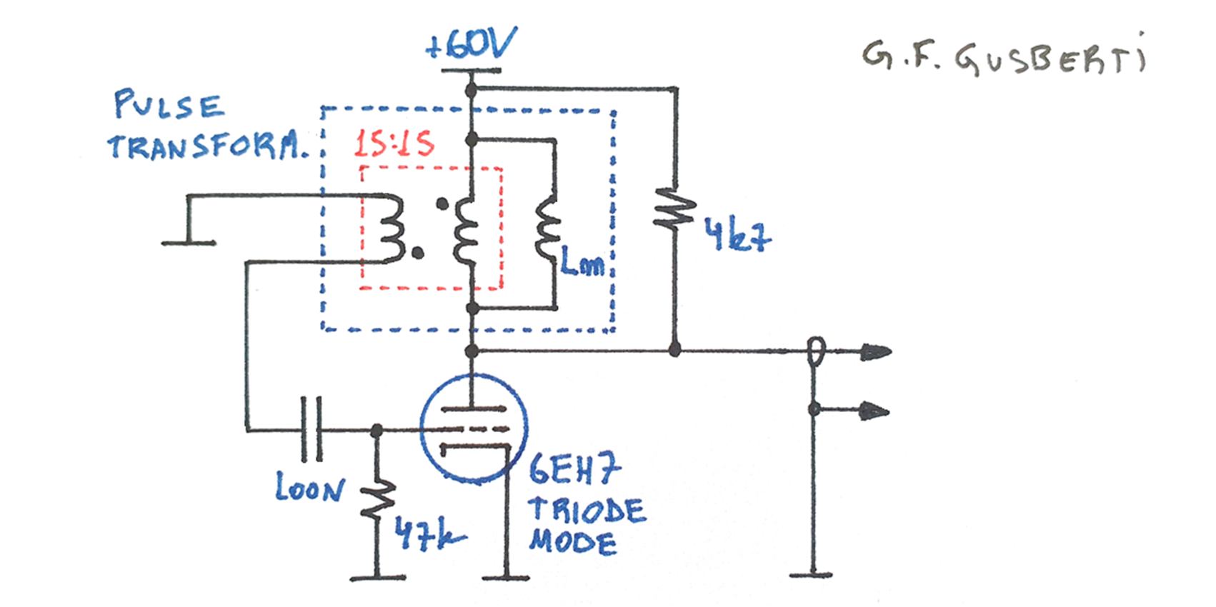
For easy of understanding, the oscillation cycle will be described in four separated sections. As the cycle repeats itself, the initial condition for step 1 will be created by the last step.
.1. CUT-OFF PERIOD
At point 1 the tube is kept in cut-off by the charge stored in the grid capacitor. The charged capacitor generates a negative biasing voltage on the grid, inhibiting the conduction of plate.
As plate voltage is constant at the supply, the pulse-transformer secondary acts as a short to ground, creating the path for current through the grid capacitor. The resistor discharges the capacitor, as seen in the grid voltage curve from point 1 to point 2.
.2. START OF CONDUCTION
When the grid voltage approaches the tube cut-off voltage (the voltage threshold for tube conduction), a small amount of plate current starts to be conducted, through the transformer primary.
The negative going edge on the plate is transferred to the grid as a positive edge, as the transformer secondary is connected in the opposite direction. This small positive excitation of the grid further increases plate current, sustaining a positive feedback condition. The tube is quickly switched from cut-off to saturation.
When the grid voltage becomes positive, the forward path from the grid to cathode becomes of low resistance, and the capacitor is charged by the transfer of energy from plate to grid. The grid loses control of plate current as it now behaves like a forward biased diode, while the tube is conducting the maximum plate current it can, this is seen as the constant grid voltage at point 3.
.3. FORWARD CONDUCTION
During forward conduction - where the tube is in strong saturation - the voltage reaches a constant plateau. As plate to supply voltage is constant and appears across the transformer, the magnetizing current increases linearly (the voltage to current transfer function of an inductance has an integral form).
During all this part of the cycle, all current flowing into the grid charges the grid capacitor as it flows through. This charge, generated by the current entering the left side and leaving at the grid side, will present itself as the negative cut-off voltage at the blocking part of the cycle.
At the same time, the magnetizing inductance steals current from the secondary-side of the pulse transformer, creating a linear drop in secondary current as the magnetizing current increases.
At the end of the conduction part, the secondary current approaches zero, and the voltage across the grid - that was supported by the forward current - begins to drop. With zero secondary current, the capacitor - that now is charged - dominates the grid voltage, reducing it bellow cut-off.
A combination of positive feedback and stored energy on the core's magnetizing inductance will now switch the tube state very fast.
.4. END OF CONDUCTION
With the tube entering into cut-off, plate current is reduced to zero. The energy stored in the magnetizing inductance of the core will continue to force the flow of magnetizing current in the same direction.
The majority of this magnetizing current is forced through the primary winding of the ideal-transformer. Note that now, the current into the primary enters the bottom of the coil (as it leaves the bottom of the magnetizing inductance).
This inversion of current flow into the primary reverses the primary voltage, creating a strong negative voltage in the secondary side. This enhances the positive feedback action helping with a very fast falling edge on the grid, switching the tube into the blocking state in a few nanoseconds.
The inductive negative voltage peak dissipates all core magnetizing energy into parasitics of the circuit. This high negative excursion is reflected to the primary as a positive pulse, that also helps with the dissipation of core energy into the parasitics of the primary side (plate resistance and output impedance).
When the pulse ceases, the capacitor is already charged and the cycle reaches the starting point 1. The circuit proceeds to start a new oscillation cycle.