
Parametric Frequency Divider
Parametric amplifiers and frequency dividers are a class of devices less known by RF enthusiasts. Modulation of some parameter of the circuit, commonly the active gain or the resonant susceptances, enables amplification by energy pumping or sub-harmonic oscillation.
In this article, we use parametric sub-harmonic oscillation to create a microwave frequency divider, where a phase-shifter filter has its capacitances modulated by the input signal.
For normal or sub-harmonic oscillators, two main ways of parametric excitation are possible. Modulation of the loop gain using bias variation or mixing and modulation of the resonant tank, where the parameter excited is commonly the susceptance of the varactors.
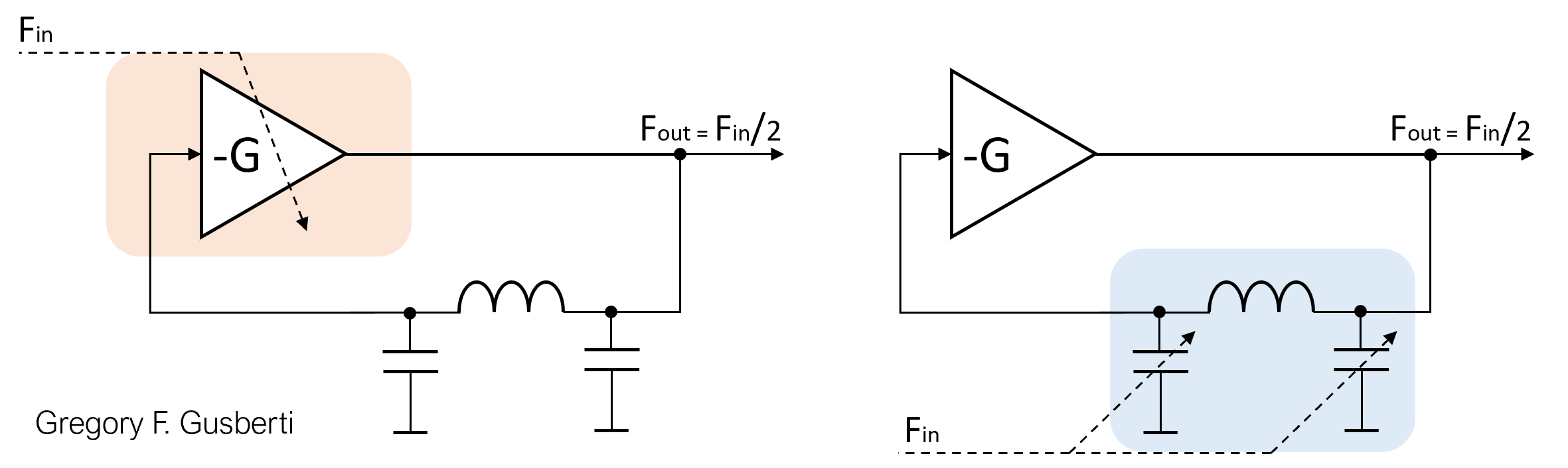
If the loop gain is modulated, the system becomes similar to and the frequency division effect occurs as the Regenerative Frequency Divider.
The main idea of the sub-harmonic oscillator comes from the non-linear effect caused by the changes in the chosen system parameter.
As the parameter is modulated, energy at sub-multiples of the input frequency is generated and absorbed in the loop reactive elements. If the closed-loop natural resonant frequency is close enough to the desired output, injection lock occurs by the injected energy.
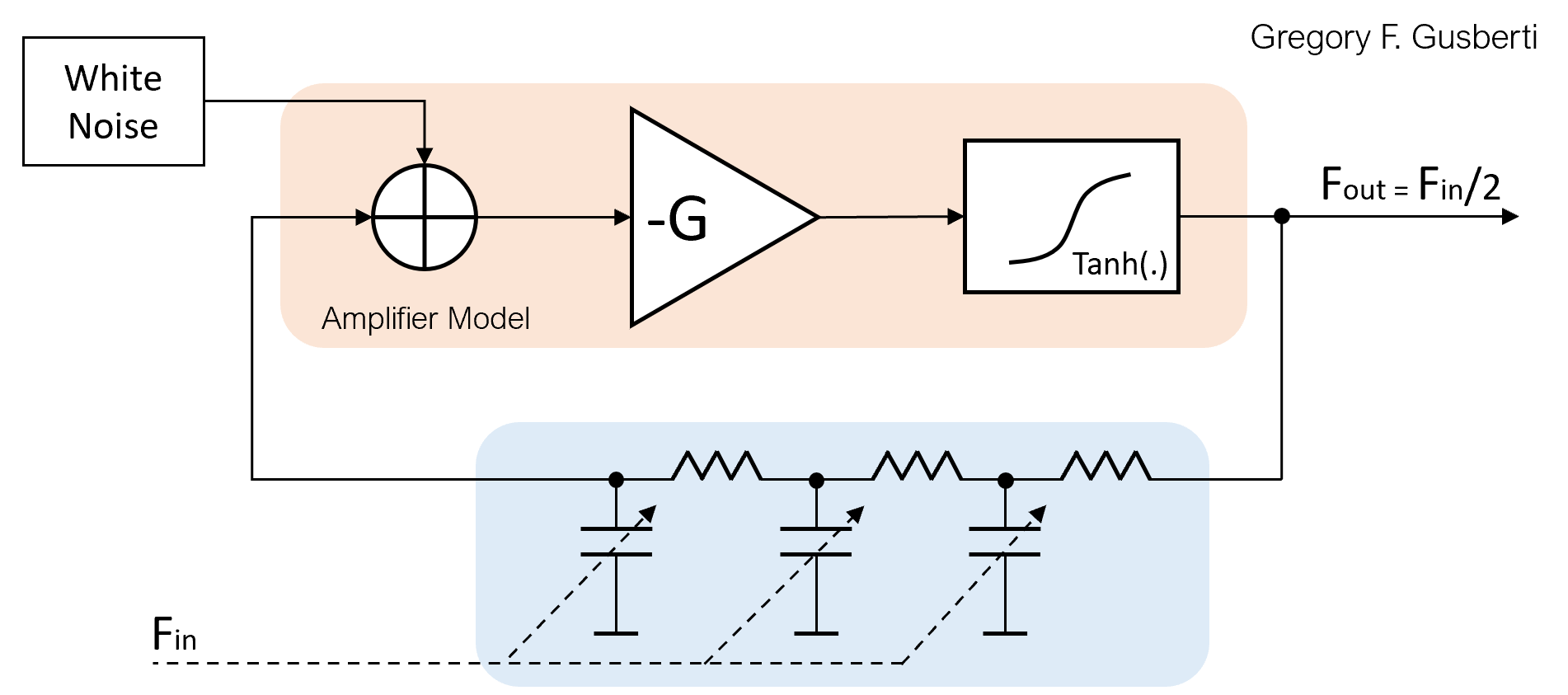
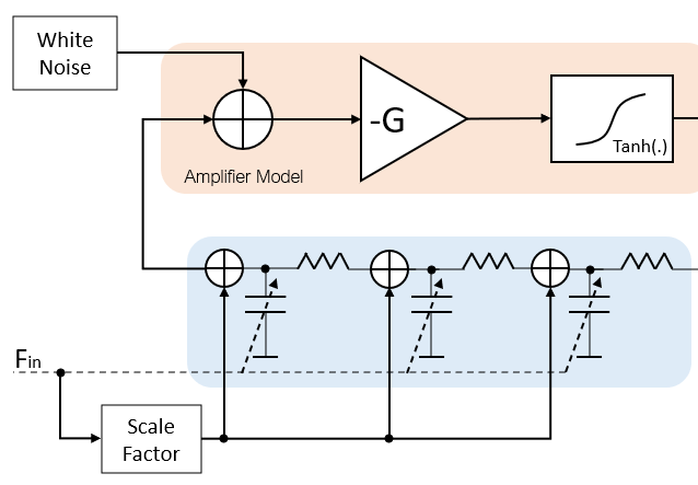
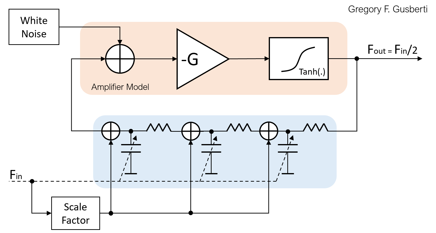
A software model of the system was created for simulation and experimentation. The active gain is composed of a linear amplification stage of gain -G, emulating the small-signal behavior of a common emitter BJT transistor. The large-signal compression is provided by the hyperbolic tangent operator, modeling the effect of stage saturation.
A white noise source excites the input of the amplifier model. A lumped source is a coarse approximation for the complex behavior of noise in active devices. However, even not being an accurate model, it is essential for simulation, as it creates the start-up condition for oscillation.
The loop filter used is a phase-shift network composed of three cascaded first-order low-pass structures. Each section provides 60 degrees of shift, where the closed-loop positive feedback condition is met by the total 180 degrees. The cascaded structure has a simple representation in discrete-time domain, enabling easy parametric modulation of the RC constant.
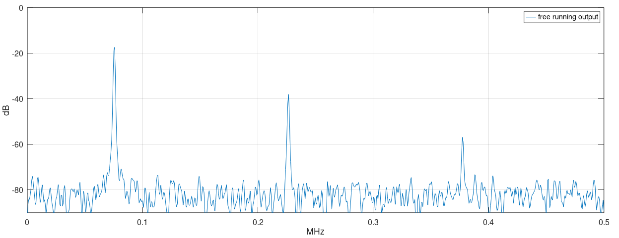
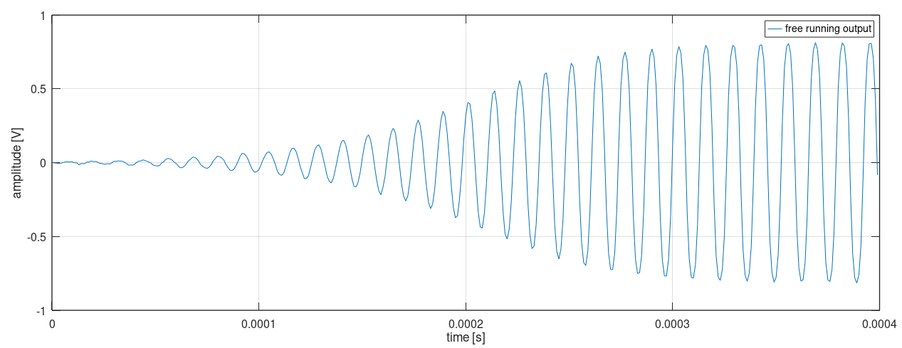
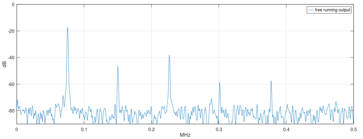
The RC constants were calculated for a free-running oscillation of roughly 75kHz. The saturation mimics the real large-signal behavior, stabilizing the oscillator amplitude and generating output harmonics of the main frequency.
To have the circuit working as a parametric sub-harmonic oscillator, in a frequency divider architecture, an external input signal is applied, modulating the filter RC time constants. This behaves as using varactors in the filter, where the susceptance is modulated by the input signal.
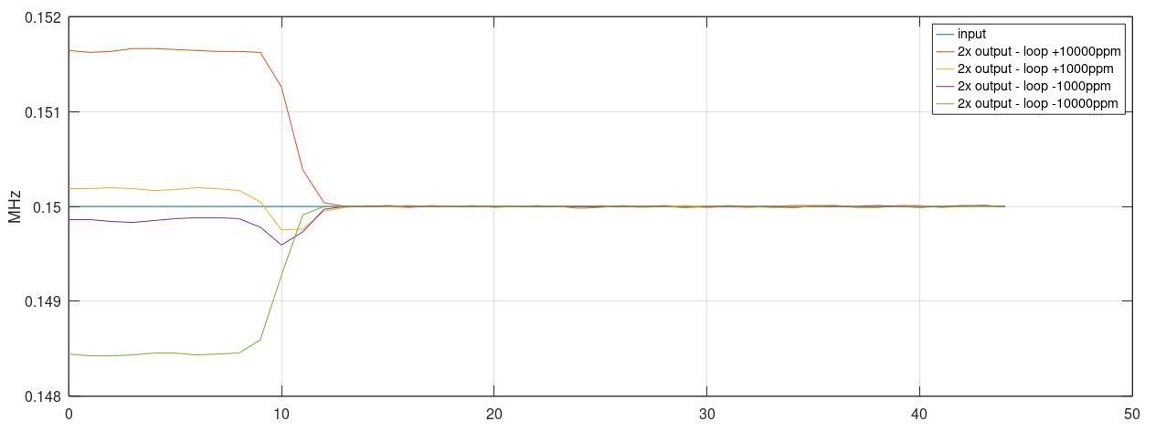
Modulation of the time constant by 4% simulates well the behavior of a filter with common varactors. For simulation, a signal of ~150kHz is used as input. The frequency difference between the input and 2x natural frequency is adjustable with a ppm factor for tests of the injection lock capability.
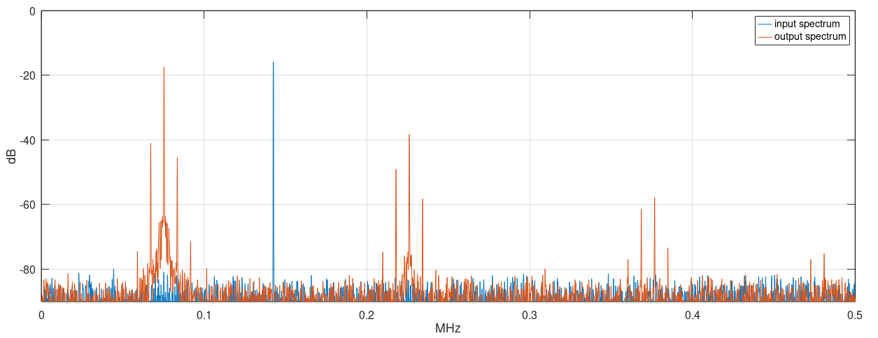
If the input frequency is very far from 2x natural frequency, the oscillator will not phase align with the input. This happens because the non-linear mixing of the input with the oscillator generates sub-harmonics far from the natural frequency, out of the injection locking range of the loop.
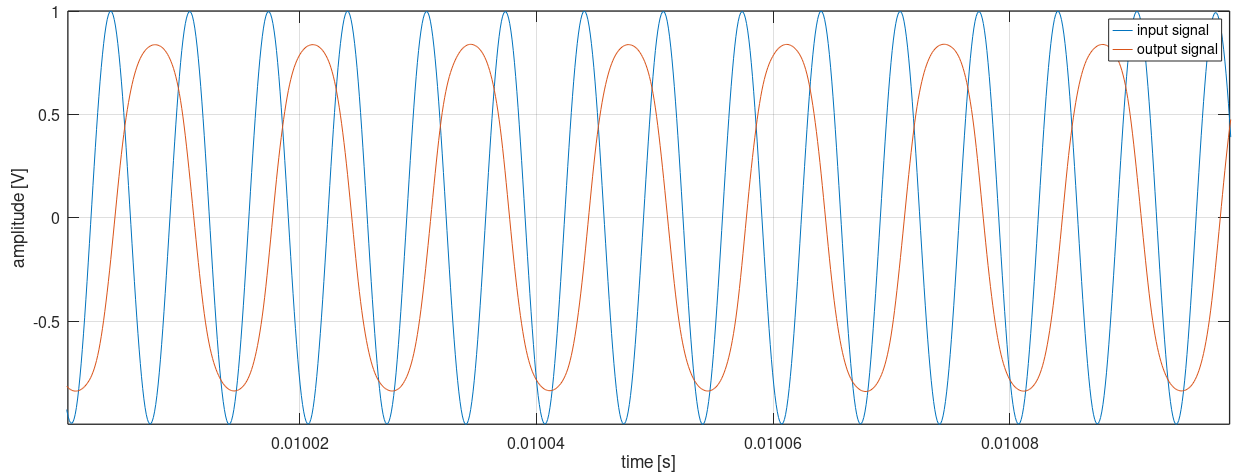
If the input frequency approaches 2x natural frequency, the oscillator readily aligns its phase to the incoming phase.
Using short-time Fourier analysis, it is possible to plot the output frequency evolution over time. The locking performance of the loop is similar for different ranges of input frequencies. For easier understanding of the responses, the input frequency is applied near sample number 10.
The parametric sub-harmonic oscillation is better understood if analyzed from the perspective of frequency mixing. The non-linear effect of changing a parameter of the system mixes the input frequency Fin with the oscillator own frequency Fo (near Fin/2 by design), by the second order mixing product of the parametric non-linearity polynomial.
An input Fin mixed with Fo (~Fin/2) generates two spectral energies at the sum and difference frequencies: Fin + ~Fin/2 ≈ 3Fin/2 and Fin - ~Fin/2 ≈ Fin/2.
Energy at ~3Fin/2 is out of the loop bandwidth and is attenuated. Energy at ~Fin/2 lands near Fo, locking the oscillator by injection.
After all, the energy at the input frequency is downconverted to Fin/2, where it is pumped to the loop and enhanced by the positive feedback.
A real circuit would not permit the modulation of the capacitances without injecting part of the input signal directly over the varactors without using complicated balanced structures. A modification of the simulation model allows better modeling, by adding a sample of the input signal at each varactor node.
The injection of the input signal will generate a spectral leakage at Fin in the output of the oscillator. A narrower bandwidth resonant filter would have better rejection of the input frequency.
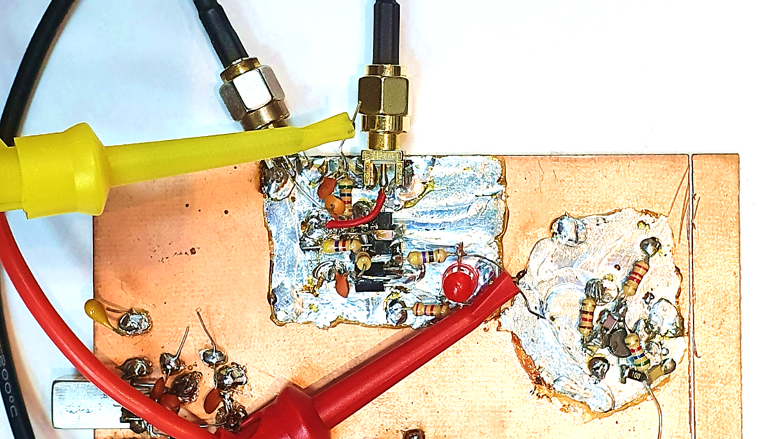
Prototype and Tests
A prototype was designed for testing and validation purposes. The circuit uses a known microwave oscillator, originally designed by S53MV. Modifications of the original design allowed parametric operation.
The input signal is applied to the varactors through the 1pF capacitor, exciting strongly the first diode. Output is taped at the output of the filter, where the second harmonic (input) is already reduced by the low pass action.
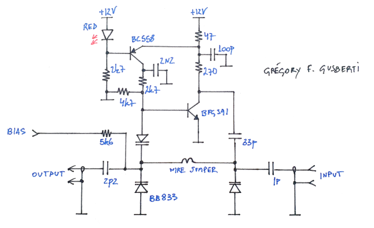
The BFG591, used in standard common-emitter configuration, works as a two port linear device, introducing active gain thus generating oscillation. The PNP transistor is a jellybean part that precisely regulates the bias of the main transistor.
For microwave frequencies, the total varactor capacitance implies a very low inductance. A small 4mm jumper wire, bridging the varactors, introduces enough inductive reactance.
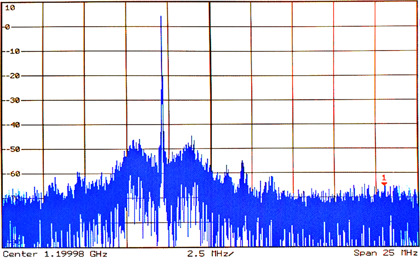
The oscillator is first tuned for free running operation, without the application of the input signal, at a near (but lower) frequency than half the input. The output signal shows an unexpected phase-noise profile, similar to a locked PLL (why?).
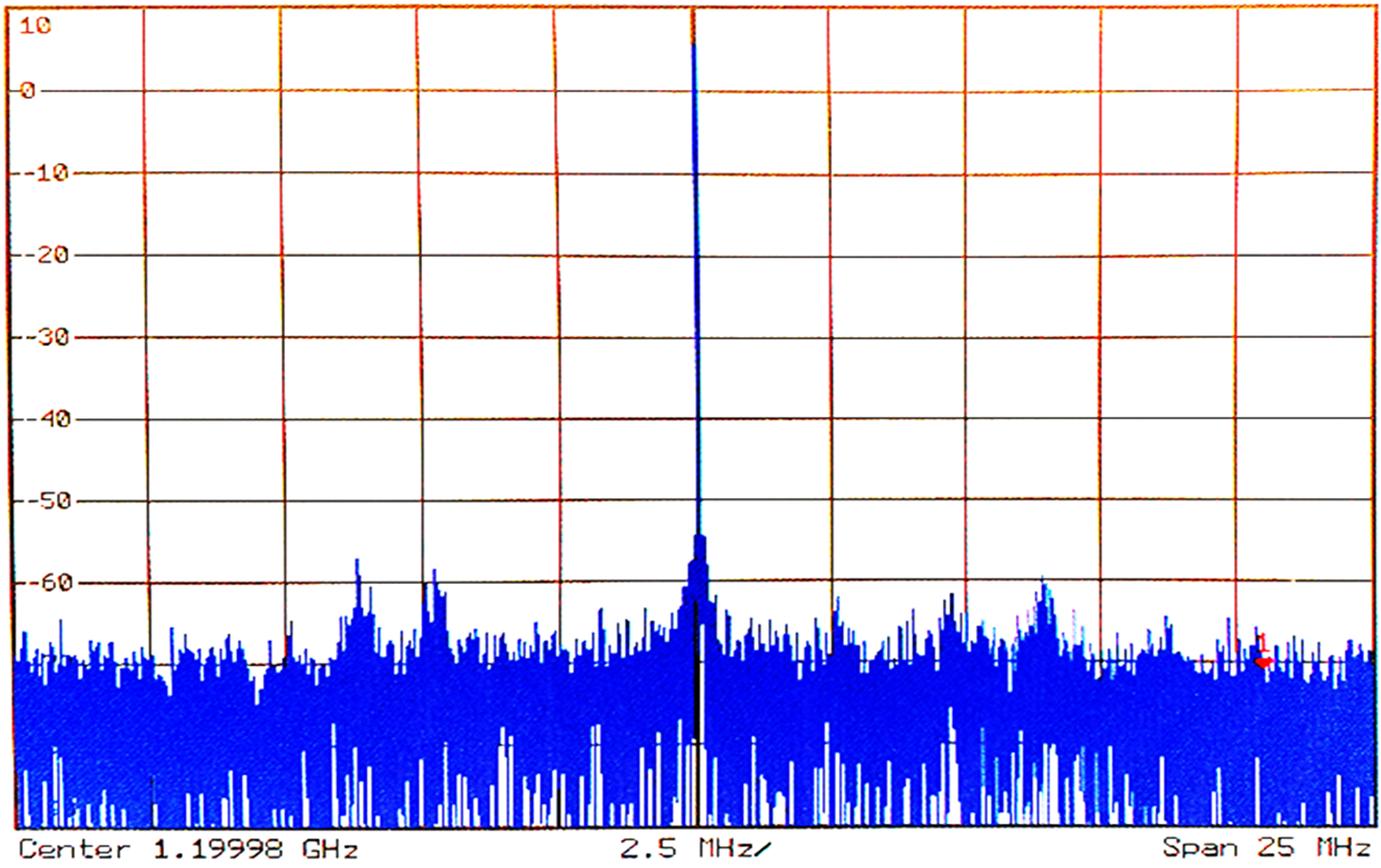
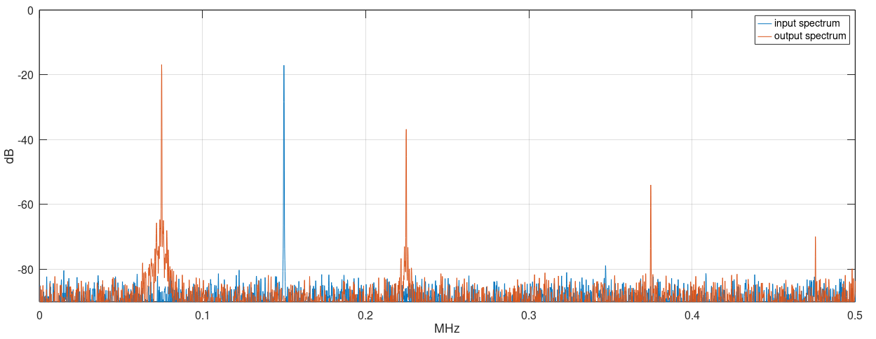
When the input signal is applied, the output suddenly jumps to half the input frequency, as predicted by the computer modeling. The parametric modulation of the varactors susceptance down-converts the input energy to half its frequency.
Injection locking of the oscillator occurs, and the parametric behavior is sustained. The output phase-noise improves, as the locking behavior reflects the better phase-noise performance of the signal generator used.
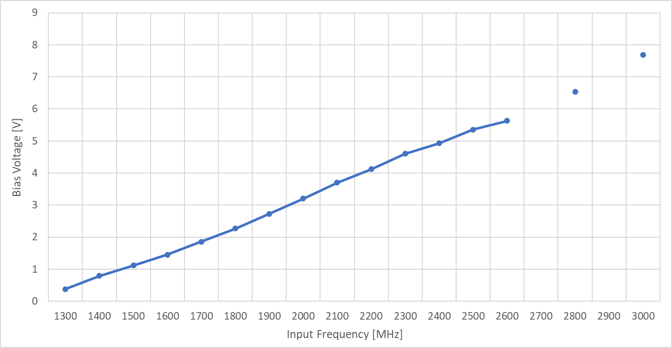
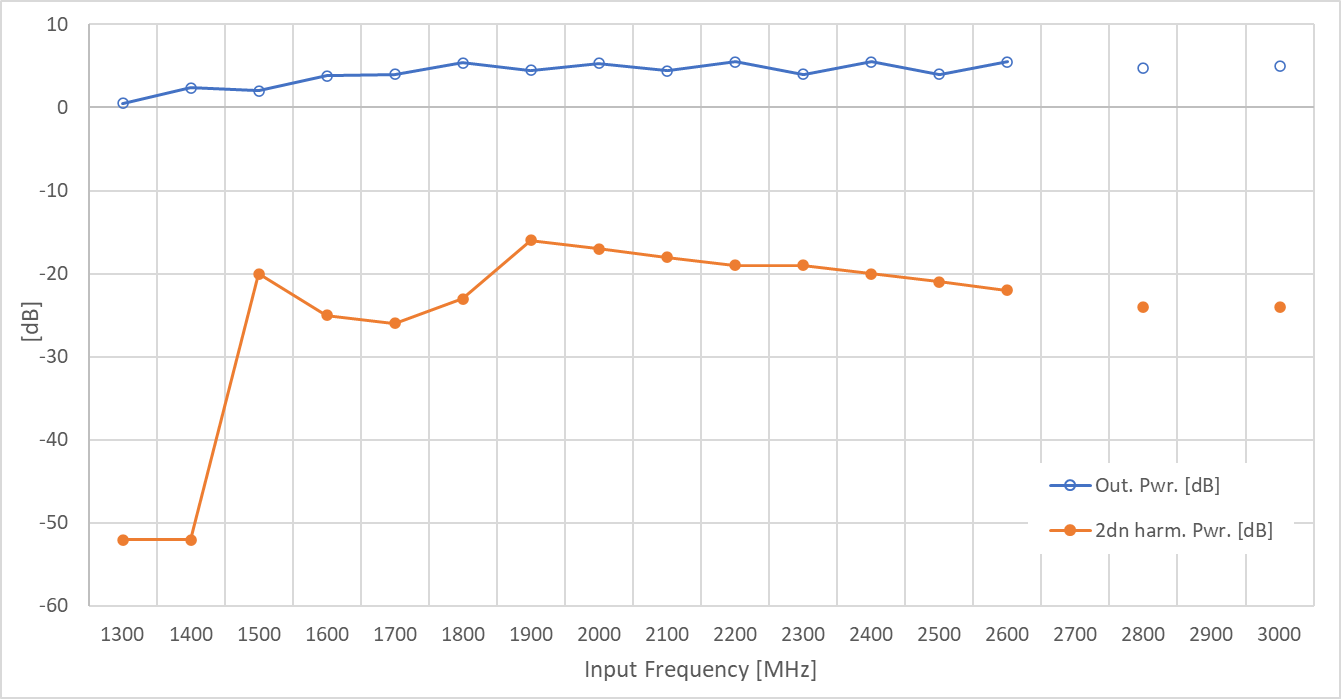
The prototype showed a wide operation band when the diodes were correctly biased, working as predicted with input frequencies from 1300MHz to 3000MHz (outputs from 600MHz to 1500MHz).
Explanation video
References
https://www.nii.ac.jp/qis/first-quantum/forStudents/lecture/pdf/noise/chapter11.pdf
https://en.wikipedia.org/wiki/Parametric_oscillator
https://www.rp-photonics.com/parametric_amplification.html
https://arxiv.org/abs/2108.10471
https://en.wikipedia.org/wiki/Injection_locking