
Discussion about gyrator oscillator and NIC
Hey guys, I'm creating this thread to archive what I discovered about the gyrator oscillator.
The motivation came from a follower of mine. He had the idea to create a bode plotter. This kind of system demands a wide range VFO.
My mind sparkled with the idea of using a gyrator and a NIC to create a virtual LC tank resonator.
After some thinking I saw that maybe with a modified gyrator, using ideas from the standard Negative Impedance Converter opamp configuration, we could sustain spontaneous oscillation by inverting the series resistance of the simulated inductor.
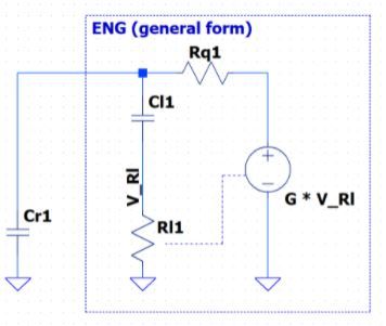
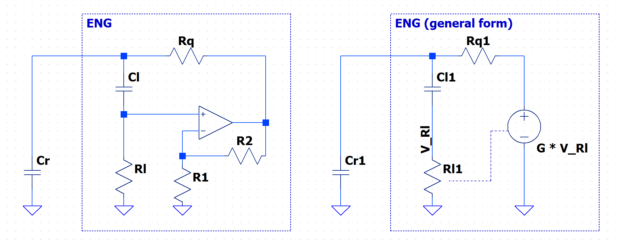
With help of other follower we derived the new equations for what I named the Extended NIC Gyrator (ENG).
The simplified equation of the impedance presented at the ENG port can be seen below as:

We can notice that with a gain larger than unit we can invert the polarity of the gyrator L series resistance and achieve oscillation.
The main theoretical advantage of a gyrator circuit in a VFO is that the frequency can be adjusted in a wide range by changes in Rl, using some kind of active device life a Field Effect Transistor.
It seems to me that the bigger disadvantage of the ENG is that the imaginary part of the impedance will also be controlled by the gain. The real effects of this interdependence are yet not understood.
It's important to have in mind that the gyrator will also present a parasitic RC impedance in its port and in the ENG it is not different. The precise equation for the impedance will be:

With more algebraic work it could be possible to use an imaginary G (a gain vector) to isolate the real Rq of the imaginary part. In a practical circuit this gain vector can be generated by complex impedance in the form of RC network.
One possible limitation of this method is that the positive gain configuration of the opamp will always present a unitary gain in its equation, as the standard gain of this topology is G = 1 + R2 / R1.
So guys, we can discuss it more on a future post. What do you think?