
Transistor Capacitance Neutralization
In the vacuum tube era and in the early days of transistors, engineers struggled to achieve the highest performance from each amplifier stage. This was done because cost of active devices were prohibitive.
When dealing with common emitter stages, the frequency roll-off is primarily dominated by the feedback capacitance. Any parasitic capacitance, from the active device and circuit, present between the output and input, is multiplied by the gain of the stage, generating a dominant pole of very low frequency.
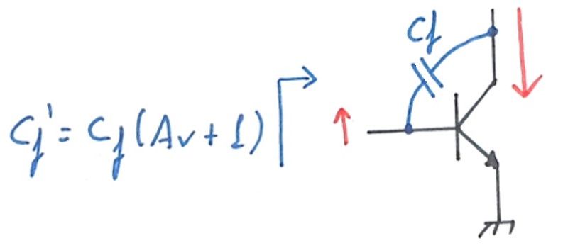
The red arrows symbolize the effect of a small signal at the base of the transistor. In this example, an upward wiggle will swing the output in the opposite direction, downward. As the output swing is Av - the voltage gain of the stage - higher than the input, the net voltage transient seen by the capacitor is Av + 1.
As for any given input, the current entering the capacitor is Av + 1 larger, the capacitance, as seen from the input, appears multiplied by Av + 1. This behavior is known as miller effect, and the feedback capacitance is sometimes called miller capacitance.
Neutralization
One technique used by engineers of the gold era was to feedback part of the output signal back to the input, with the polarity inverted. This positive feedback scheme, if correctly tuned, can negate the effect of the feedback capacitance, as the additional feedback capacitance current is now supplied from the output.
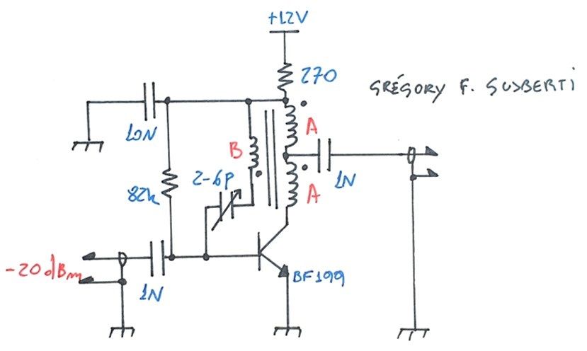
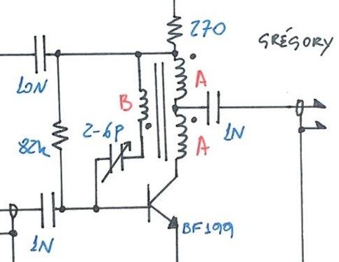
To test the concept, I designed a little broadband HF amplifier, using a BF199 transistor. The collector is biased with 10mA and I used the "A" balun to impedance match the output.
Without the neutralizing network "B", the broadband output match, provided by the balun, allowed a 26dB of small-signal gain with a 3db bandwidth of 43MHz. The input was leaved unmatched for all the testing.
Now that we know the normal gain of the stage, we connect the neutralizing network to see the difference.
To couple part of the output signal, I wound the "B" winding on the balun, using the same number of turns as "A". The feedback signal is coupled to the base using the trimmer capacitor, where tuning is needed to exactly cancel the feedback capacitance. Attention is needed in the connections to guarantee that the polarity is correct and positive feedback has taken place.
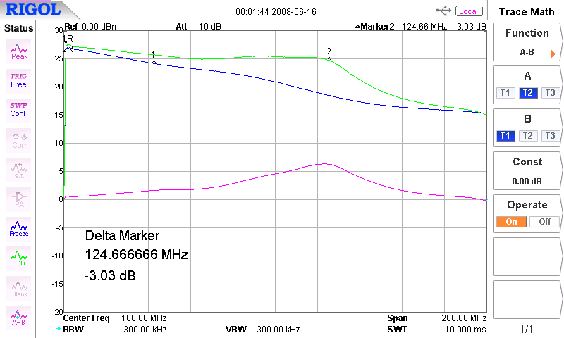
The green trace is the frequency response with neutralization in place, and the blue trace is the response without it. We can see a big improvement on the bandwidth, that was more than doubled in this test.
With neutralization, the small-signal -3dB bandwidth has extended to 124MHz. The purple trace shows the difference of the responses, revealing the effect of the feedback. It's interesting to see that the improvement is almost a perfect 6dB/oct, cancelling the dominant pole caused by the miller effect.
At higher frequencies, the response becomes dominated by other poles and the neutralization looses its effect. I noticed that the response is actually worse after 200MHz, probably because we reach the bandwidth knee of the balun and, as the feedback signal phase rotates, the feedback deteriorate the response.
Oscillation
Care need to be taken when tuning the variable capacitor. The positive feedback will cause oscillation if not exactly adjusted, principally is this broadband design. I used a trimmer with almost 10pF range, and the tuning range with a stable operation was small. A lower capacitance trimmer or a small 3p3 capacitor in series can help to reduce the adjustment range.
I conclude that this technique is useful only in rare situations, when more gain is needed and no other parts are available, or to reduce the input susceptance. Probably, choosing a transistor with higher transition frequency will always be a better move, as the neutralization technique is inherently less stable due to positive feedback.