
RF switch using BJT transistor

In the search for a cheap way to make RF switches in homebrew projects, I came with the idea of using a NPN transistor biased as two separated diodes.
The idea consists in the use of two opposed diode junctions to block de RF signal when the controlling voltage is zero.
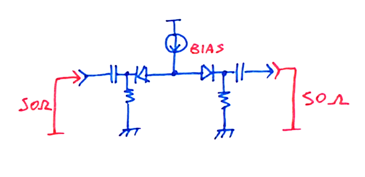
The small signal model for the off-state condition is two junction capacitances in series. As the capacitances are small, the RF signal will be virtually blocked, because the incident wave will reflect when it encounters the mismatch from the high capacitive reactance.
When a positive voltage is applied to the control port, at the center tap of the diodes, both junctions become forward biased, changing the small signal behavior.
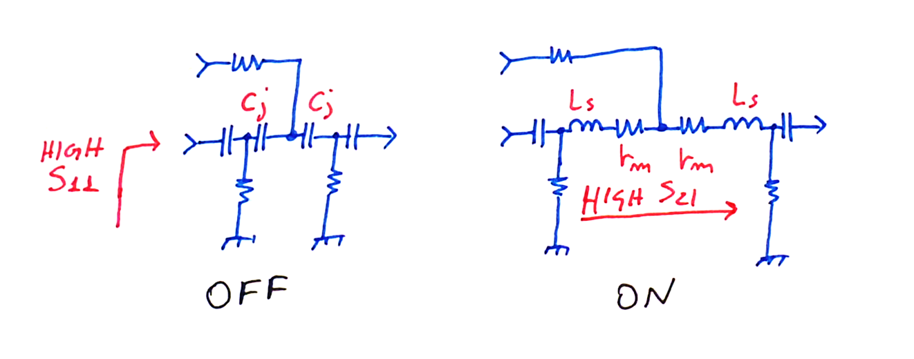
At forward bias condition, the junctions model is dominated by the low dynamic resistance and series inductance, allowing RF energy to flow from the input port to the output.
From a first degree analysis it is clear to see that the insertion loss depends directly on the dynamic resistance magnitude and the off state isolation on the junction capacitances.
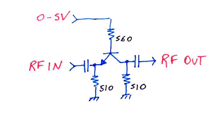
The biasing resistors were chosen to forward bias the junctions with 2.5mA each at a controlling voltage of 5V.
I tested five different transistors I got from my junk box: BC547, BF199, BFR106, BFR92A and BFP420.
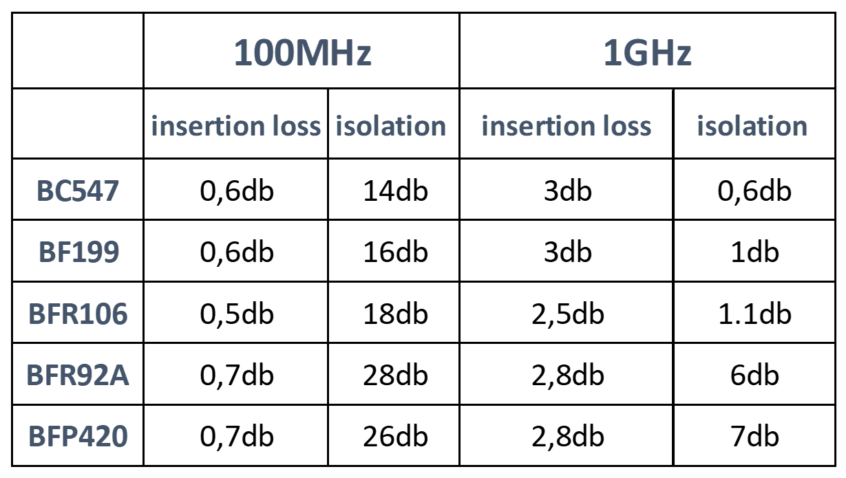
The last three transistors are for use at microwave bands. Having much lower junction capacitances, the high frequency transistors made better RF switches.
This concept seems to work well for VHF and maybe lower UHF frequencies, because, as it can be seen, at 1GHz the performance is less than desired, showing low isolation and increased loss.
It is then up to the reader to test whether this arrangement could be used as an RF output amplitude modulator, as suggest by the circuit below.
