Overtone Crystal Oscillator
Oscillation at an overtone frequency allows a crystal oscillator to run at an odd multiple of the main crystal frequency (3f, 5f, 7f). This is a simple way to frequency multiplication in crystal oscillators.
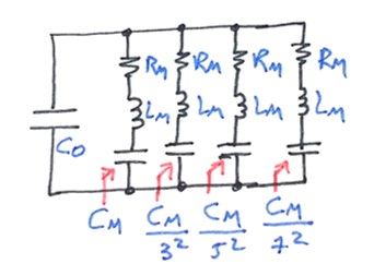
Odd modes of operation are possible because of the mechanical construction of common AT crystals. From an electrical perspective, the crystal presents multiple series resonance modes, where the motional inductance is maintained, and the motional capacitance is reduced by the overtone index squared.
The parallel parasitic capacitance, responsible for the parallel resonance mode, is virtually unchanged by overtone operation.
The oscillator circuit needs to be designed to maximize the starting gain right at the overtone frequency desired at the output, providing the correct phase delay to sustain the oscillation behavior.
I started my design using a common-base topology because it maximizes the transistor high-frequency performance, reducing the miller-effect, thus increasing operational bandwidth. The BJT transistor used in this example is a BF199.
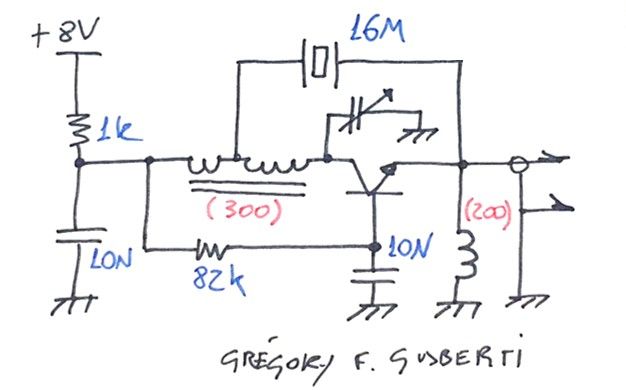
The bias condition is generated by the 82k base resistor and the 1k resistor in series with the power supply. Bias stability is granted by feedback mechanism at the collector DC potential, providing 1mA of collector current.
The collector AC load is a resonant tank tuned to the desired overtone frequency. The tank inductor is taped at the 1/3 from the cold end, providing a low impedance connection to the crystal, thus increasing circuit loaded Q.
The variable capacitor provides the tuning capability of the circuit. This test circuit was easily tuned at the 3rd, 5th and 7th overtone by small adjusts. I used a 16MHz crystal, so the possible output frequencies were 48, 80 and 112Mhz.
In red and in between parenthesis are reactances I recommend for the two inductors, at the desired frequency. With this, the needed inductance can be calculated, and the tuning capacitor chosen to resonate the tank inductance.
The crystal feedbacks the signal to the transistor emitter, closing the loop. The high loaded Q guarantee that the peak gain will be at the tuned overtone frequency, sustaining proper oscillation.
Different from the most common approaches, I used an inductive reactance in the emitter of the transistor. This provided much better tuning capability and better frequency stability.
Being part of the circuit resonance, fed back power that is not at the desired frequency is shunted to ground, reducing the gain at sidebands of the overtone frequency. Putting an emitter resistor in the place of the inductor, as more common, turned the circuit difficult to tune and generated spontaneous oscillation at all the tuning range of the tank.
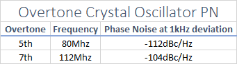
Phase Noise
Phase noise was measured at the 5th and 7th overtones. The 7th harmonic phase noise was worse than the theoretical reduction of 20*log(7/5), as it can be seen below.