
Nonlinear amplifiers: Saleh model
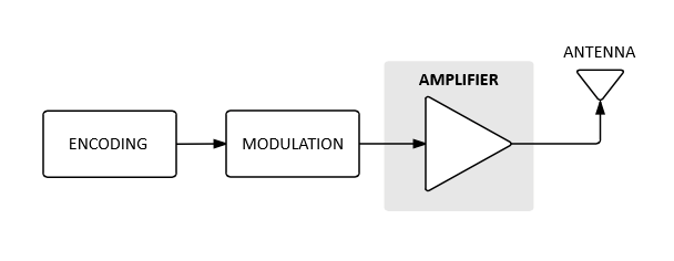
In most modulation systems, for transmission over long distances, high power amplifiers are used at the output. Large amplifiers are intrinsically nonlinear, due to their class of operation and the trade-off of linearity vs. efficiency of the design.
Nonlinear models are every engineer's nightmare. In the field of communications, such systems distort the transmitted signal, generating spectrum leakage, modulation errors and, consequently, a lower maximum data rate on the link.
Predominantly, the power amplifiers are responsible for generating the greatest distortions in a transmission system. The signal delivered by the modulator is usually generated digitally, being free of spurious and correctly contained in the spectrum. However, when delivered to the PA, the output behavior is not only the amplified signal, presenting spurs, skirts and other distortion effects.
Ideal Amplifier
An ideal amplifier can be model as a linear amplitude (AM/AM) gain, such that it boosts the signal to the desired level, and a zero phase (PM/AM) gain. Therefore, it is clear that its effect on the system will be to intensify the signal without distorting it, possibly adding a permanent and stable delay/phase shift.
Saleh Amplifier Model
The Saleh model represents the nonlinearity of an amplifier by two gain factors: amplitude-amplitude – AM/AM – and amplitude-phase – PM/AM. Such factors model the PM and AM error generated by a given input signal with known amplitude. It is observed that both transfer functions have the input magnitude as a denominator, a characteristic of Saleh nonlinear model.
The amplitude-amplitude and amplitude-phase factors will be determined by the unique behavior of the amplifier in question, and are represented by defines A, B, Alpha and Beta. Such constants can be extracted from the amplifier S parameters, given the operating conditions, and are related to the AM/AM and PM/AM factors by the equations:
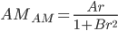
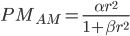
The argument r is the instantaneous amplitude of the signal exciting the amplifier. As an example, an amplifier modeled by the Saleh method that uses the coefficients:

has these AM/AM and PM/AM transfer functions:
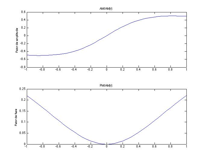
The top plot shows the compression of the amplifier, pointing out the saturation point that leads to signal distortion On the other hand, the phase factor is almost linear and denotes an increase in phase as the signal amplitude shifts over zero.
Effects on a digital constellation
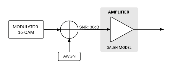
The other way of visualizing the distortion generated by nonlinearity is by applying the model to the output of a modulator, observing the output baseband constellation.
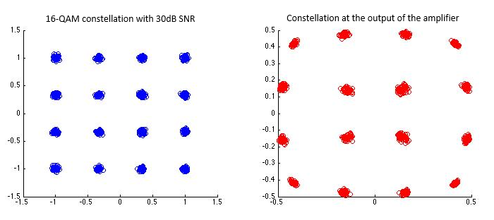
This method clearly demonstrates the transmitted signal and the challenge the receiver has when decoding the signal. In the proposed experiment, Gaussian white noise was also added, simulating a 30dB SNR in the system, improving the perception of distortion to the naked eye.
Let's see below the 16-QAM constellation that enters the amplifier and the corresponding output distorted by the non-linear model.
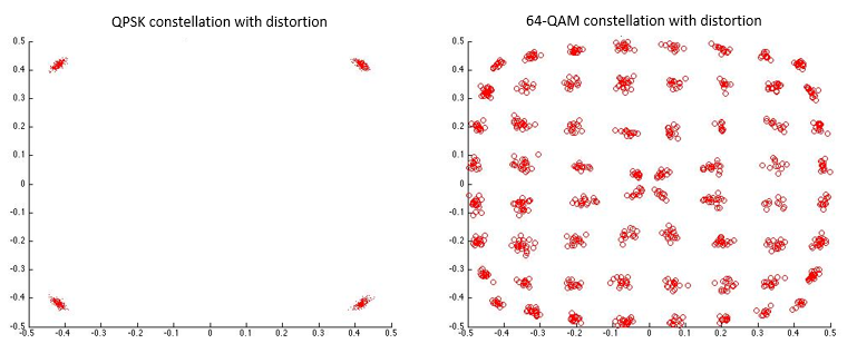
Below, we see the same experiment with QPSK and 64-QAM constellations, respectively.
Pre-Distortion
Several topologies were developed to mitigate the effects of non-linear amplifiers, including pre-distortion. With the use of pre-distortion, we can alter the signal sent to the amplifier so that, when distorted, the output lies on the correct point.
Adaptative techniques or genetic algorithms can be used to estimate, in real time, the coefficients that model the amplifier. Of course, such characteristics can be measured on the shop floor and stored in memory. However, the last option does not compensate for possible variations that may occur due to thermal effects or operational changes.
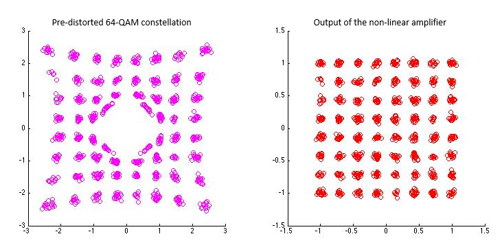
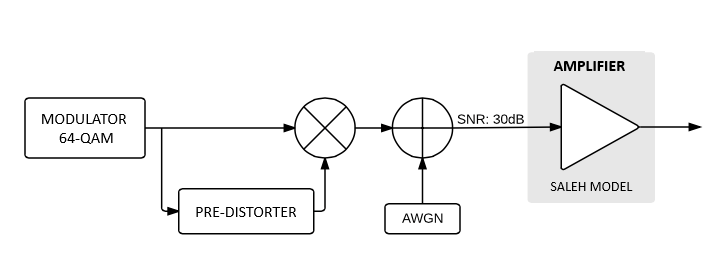
In the following example, I will use a feedforward digital pre-distortion topology. The pre-distorter analyzes the symbol coming from the modulator and pre-distorts the constellation in order to cancel out the effects of the amplifier.
In this example, the pre-distortion uses a symbol-indexed LUT, mixing the correction value into the IQ stream. Another way of implementation could be the pre-calculation of mapper LUT, considering the transfer function of the amplifier.
Results obtained with correct pre-distortion:

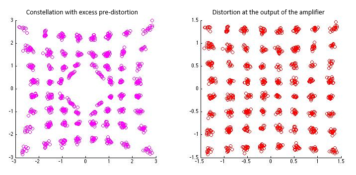
In the case of excess pre-distortion, constellation distortion will also occur, causing the same problems as a non-linear amplifier. This shows that, regardless of the method adopted, great care is needed when tuning the system. With over pre-distortion, issues may occur, mainly, in feedback topologies which, naturally, can oscillate.
References
https://www.researchgate.net/publication/224517086_New_Modified_Saleh_Models_for_Memoryless_Nonlinear_Power_Amplifier_Behavioural_Modelling
https://www.derekkozel.com/talks/FOSDEM2019_Digital_PreDistortion.pdf
https://www.mathworks.com/help/comm/ug/add-saleh-mode-of-memoryless-nonlinearity-to-16qam-signal.html
https://rfmw.em.keysight.com//wireless/helpfiles/n7614/Content/Main/Digital Pre-Distortion (DPD) Concept.htm