
DSSS BPSK Beacon

This article describes the development and working principles behind a discrete Spread Spectrum BPSK beacon. The designed system consists of a reference oscillator, frequency multiplier, binary phase-modulator and digital microcontroller, integrated on a single PCB. The presented architecture could easily be implemented in CubeSats or for terrestrial monitoring of distant sensors.
The performance of narrowband communications can be enhanced by artificially spreading the original signal over a wide bandwidth. DSSS - Direct Sequence Spread Spectrum - utilizes a pseudo-random code, with a much faster rate than the data, to enlarge the bandwidth of the original signal.
The spread signal, sometimes occupying a bandwidth several orders of magnitude higher, is decoded in the receiver by a despreading operation, where the received spectrum is collapsed to the original bandwidth and the signal recovered. The end-to-end effect, governed by mathematical correlation principles, is that narrowband interferences and distortion affects the link as thermal noise would.
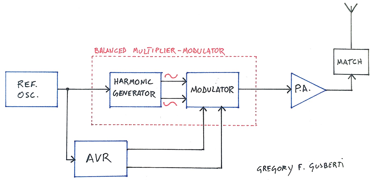
The developed beacon consists of the digital microcontroller, where the data payload is encoded with the spreading code, a local oscillator, frequency multiplier/phase modulator and PA. For experimental tests, the payload is kept as a constant ASCII message, that for general usage would be replaced by some useful non-deterministic data.
The main goal of this design was the construction of a discrete system, using jellybean parts. The binary phase-modulation process, that commonly is accomplished by a diode-ring balanced modulator, was embedded in the frequency multiplication circuit, reducing the project parts count.
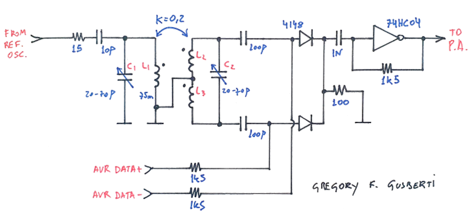
The reference frequency is harmonic multiplied to the desired output band. The double-resonant tank is constructed with a balanced output inductor, where the ground is connected at the L2/L3 center tap. C1 tunes the primary inductance L1, and C2 tunes the secondary side inductance.
The 10p capacitor loosely couples the oscillator signal to the L1/C1 tank. The 15r resistor damps oscillations at anharmonic frequencies.
In the designed prototype, a 16MHz oscillator is used, allowing the selection of harmonics in the HF bands of 48, 64, 80, 96 and 112MHz.
The two tanks are air coupled with a weak coupling, this is accomplished by the mechanical position of the inductors at the PCB. An improvement of the current prototype would be an even weaker coupling, enhancing the frequency selectivity of the desired output harmonic.
The balanced architecture directly outputs the two phases needed for a BPSK modulation. Modulation is simplified by an RF SPDT diode switch. The diodes are used to select which phase (0/180deg) excites the PA. The diodes are biased directly by the AVR, using the 1k5 resistors. The modulation stream is generated differentially on firmware, and switches the upper and bottom diode in opposite phase.
An 74HC04 CMOS inverter, biased in the linear region, serves as an exciter to the PA. The linear gain brings the signal level of the multiplier/modulator to the logic levels needed by the output amplifier.
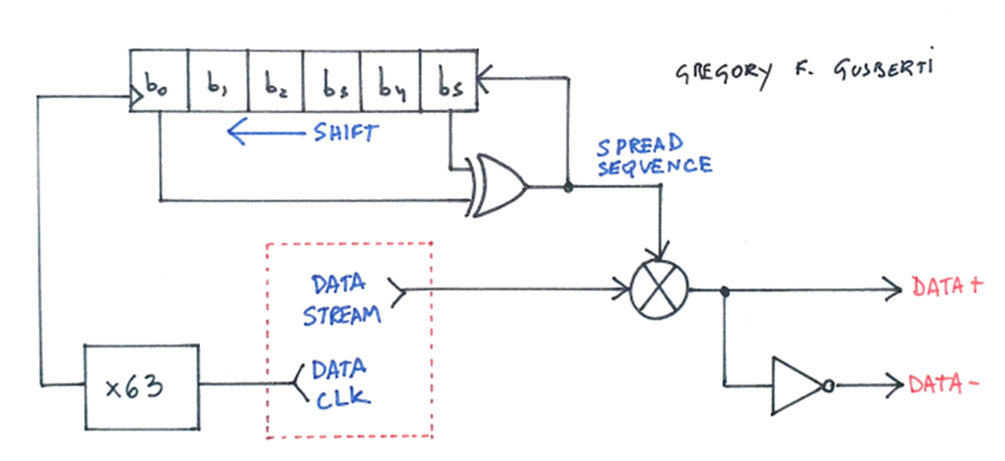
The AVR firmware is responsible for the DSSS modulation. A software LFRS is used for the generation of the spread sequence. The prototype uses a 6 bit register, with taps configured to generate a maximum-length sequence of 63 bits. A latter update of the code replaced the LFRS by a table with the pre-computed sequence.
Each data bit clock advances a full sequence of the LFRS, enlarging the original data rate by 63 times. The firmware outputs the modulation stream in differential form, switching the modulator diodes directly.
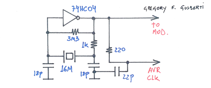
The reference signal comes from a simple Pierce oscillator. A low-pass tap helps to isolate the RF and digital sections, feeding the AVR clock input. This synchronizes the RF output with the firmware execution, which could facilitate the demodulation process at the receiver side.
A different crystal could bring the output signal to an allowed ham radio band.
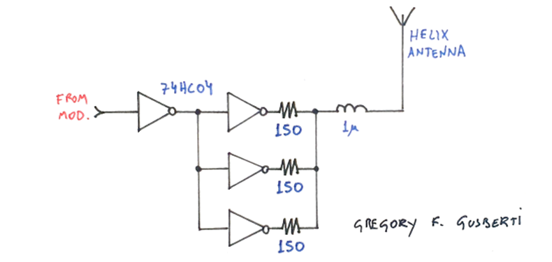
A simple PA was created using the remaining logic gates of the 74HC04 integrated circuit. Three gates with output resistors creates a decent 50ohm output.
The helix antenna was matched to the circuit using a 1uH inductor, as the natural resonance of the short antenna was higher than the desired output frequency of 96MHz. A self-resonant antenna would not fit the prototype size.
For commercial use, this PA is not suitable. The output signal is rich in harmonics, generated by the near square wave output of the logic gate. An output low-pass filter, of at least 5th order, would improve the spectral leakage and could also incorporate the antenna match impedance transformation.
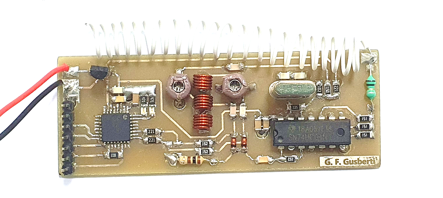
The prototype was constructed using a dual layer FR4 PCB, where the bottom is used as a ground plane. The harmonic frequency multiplier is easily seen in the center of the board. The weak coupling between the tank inductors is accomplished by the distance between them.
The two 1N4148 signal diodes are placed near the multiplier output, and the AC coupled RF output feeds the 74HC04 exciter gate.
Two LEDs were placed near the AVR, serving as visual indication of the firmware status. A 78L05 voltage regulator supplies 5V to the AVR and also to the HC04 integrated circuit. The pin header at the left of the board enables easy connection of an Atmel ICE, for in-circuit programming.
Demodulation with SDR
A complete Software Defined Radio Spread Spectrum Receiver was developed in JavaScript, using a Tektronix RSA306 as the RF front-end, to decode the signal transmitted by the beacon.
References
https://www.ni.com/pt-br/innovations/white-papers/06/understanding-spread-spectrum-for-communications.html
https://www.youtube.com/watch?v=68Nua8gKdRU
http://lea.hamradio.si/~s53mv/navsats/theory.html
https://en.wikipedia.org/wiki/Spread_spectrum
https://www.gaussianwaves.com/2015/06/gold-code-generator