
BJT Active Mixer Experiments
In this post, we are going to review and understand data collected from an Active Mixer tested at the bench. The mixer was designed for the only purpose of experimenting.
Operating Principle
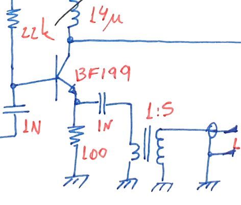
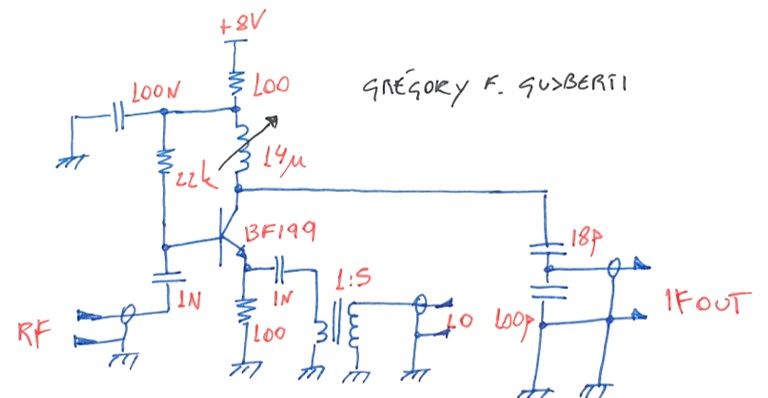
The circuit is based around a common emitter BJT amplifier, DC bias is guaranteed by the 22k base resistor, 100R top and bottom resistors. The RF port couples energy directly to the transistor base, through the 1N coupling capacitor.
The 1:5 ratio transformer is used to match the emitter, presenting something near the 50R system impedance at the LO port. For the LO signal, the BJT transistor acts as a common base stage, so input impedance is very low (1/gm + some reactance).
The AC load is the resonant tank formed by the tunable inductor, 18p and 100p capacitors. The network is made resonant at the desired output IF frequency: 10MHz in this example.
IF energy is coupled to the IF port through the capacitive tap. Tapping the capacitive divider transforms the IF port 50R impedance to near ~2k ohm at the transistor collector, increasing the loaded Q thus reducing the bandwidth of the IF output.
1dB Compression Point
The P1dB was measured using an RF power sweep at LO powers of 7dBm and 10dBm.
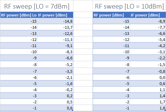
Increasing the LO to 10dBm clearly improves the conversion gain, becoming higher than unity. Opposing what we would estimate from passive mixers, the BJT mixers starts to compress earlier. This happens because the bias condition is changed as the large-signal behavior kicks in and the harmonic distortion is increased, as we will see later.
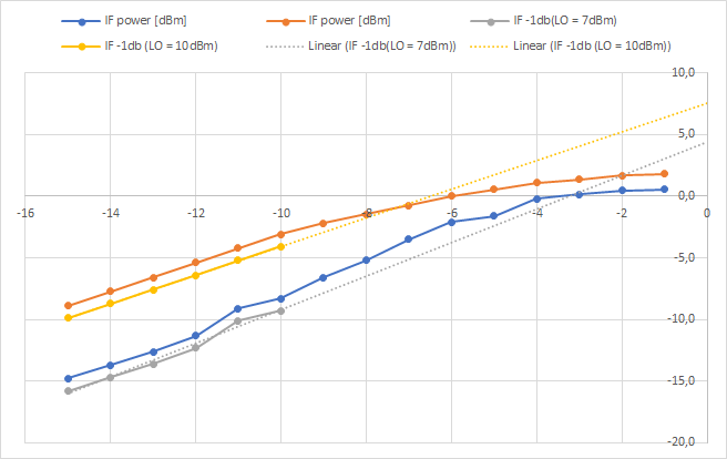
The P1dB is encountered by linear interpolating the small-signal gain minus 1dB, finding where it crosses the measurement. I used the first 6 data points as the ideal behavior of the mixer. The yellow line emulates the ideal mixer using 10dB LO and the gray line 7dBm.
With this graphing technique, the compression becomes easily spotted. For 10dBm LO the P1dB of the mixer is -7dBm and for 7dBm LO it is -3dbm. Thus, the designer will fight this trade-off between conversion gain and linearity.
IF Harmonic Distortion
An increase in LO power decreases the P1dB as we saw earlier. As the large-signal model starts to dominate the transistor behavior, power from the IF fundamental (10MHz) is shifted to higher harmonics. This can be confirmed comparing the 2nd IF harmonic power in relation to the fundamental tone.
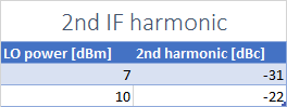
With a 10dBm LO the second harmonic approach the fundamental by almost 10dB.
Third Order Intercept
The IIP3 was measured using two signal generators and a 6db power combiner. Two tones spaced closed apart were injected at the RF port, while the intercept point measured with the help of a spectrum analyzer. To help the understanding of the behavior, I swept the LO power, graphing the IIP3 at each step.
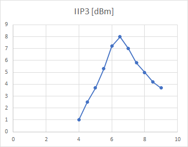
As we could imagine, TOI is maximized at a specific operation condition, and it happens to be near the 7dBm LO. Lower and higher LO signals degrades the mixer performance. As predicted by the math, the TOI of 8dBm is very close to the analytical prediction of 7dBm (P1dB + 10dB).
The analytical prediction is also spot on when the 10dBm LO is used. The predicted TOI of P1dB + 10dB is 3dBm, agreeing with the measurements.
I also recorded a video explaining all the methods used in this characterization in more detail.