
Garage Remote Control - Range Improvement
Remote controls for garage doors are designed as low-cost devices, using very low part counts, and with small size for portability. These constraints commonly reflect in an RF system with low performance (low range and/or low battery life).
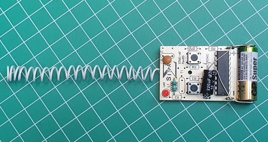
This article explains the RF section of a remote control and the addition of a helix antenna for increased range.
Different protocols and modulations are used for controlling garage doors. This control utilizes one of the simplest forms: a 12 bit code transmitted with OOK, at a 300 MHz carrier.
OOK modulation stands for On-Off Keying, where the RF carrier is turned on and off with the data signal - a special case o binary AM modulation with 100% modulation index. Even with bad RF performance - high spectral leakage - the signal can easily be received by the garage door motor, using a super-regenerative receiver.
The IC shifts the binary sequence directly on the base of the RF transistor, turning the oscillator on and off, accordingly to the data. The oscillator needs to start up in a fraction of the bit period, reducing the opportunity for high Q oscillators, as oscillators startup times are proportional to Q.
The combined need for low Q, low complexity and low cost, is accomplished with a single transistor oscillator, made by a combination of lumped and printed components.
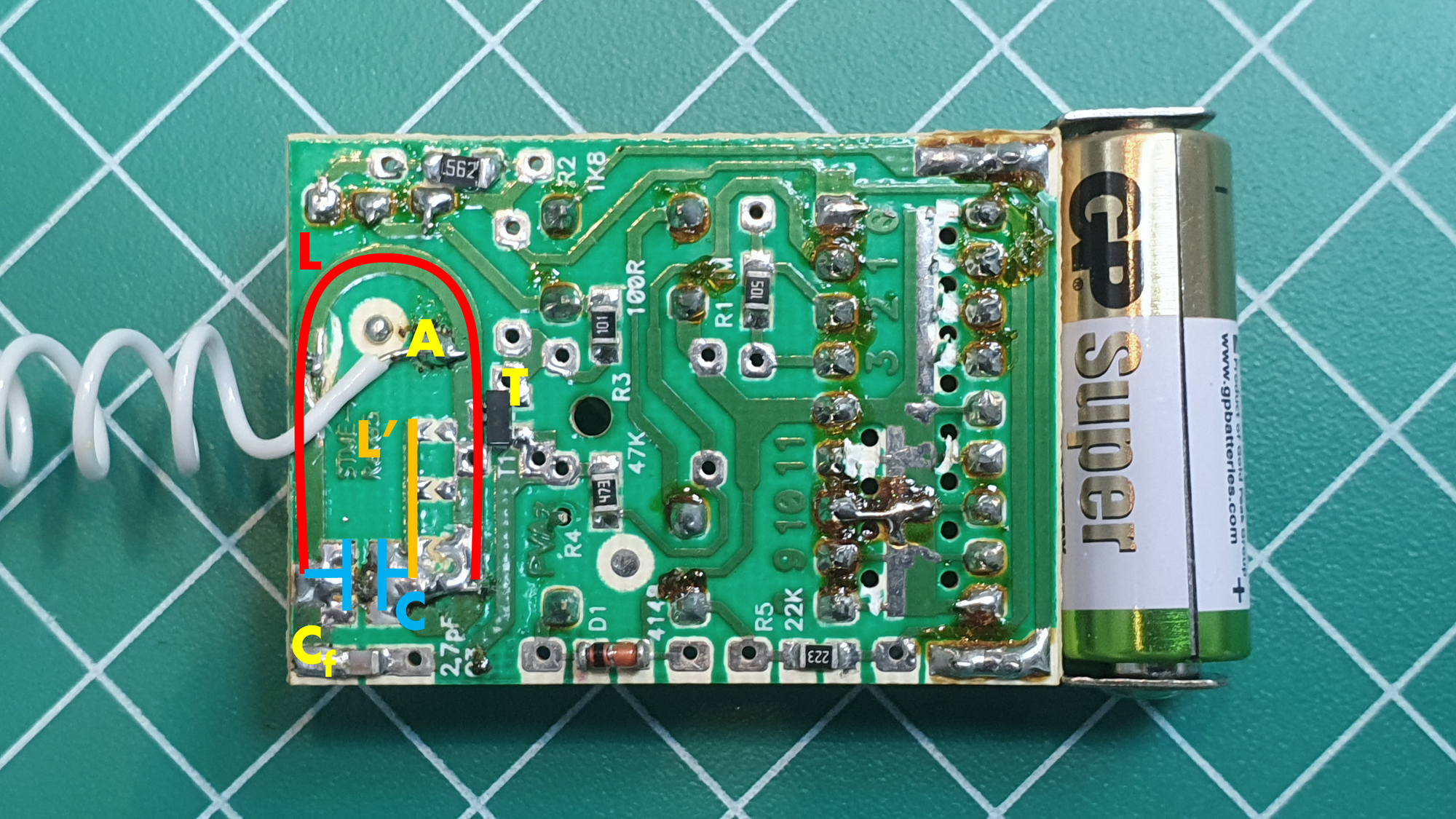
The transistor works in common-emitter configuration, with the emitter degenerated by 100 ohms. The collector is loaded with a resonant tank, made by L and C, where C is a through hole capacitor and L is a printed inductor. The SMD capacitor Cf, of 2.7 pF, feedbacks power from the resonant tank to the base of the transistor, sustaining the positive feedback action needed for oscillation.
In the original remote design, the printed L inductor also works as a crude antenna, that works well for very short distances.
The connection A - where the added antenna is connected - is the biasing point for the collector, with a through hole inductor (on the top of the PCB) feeding DC power to the oscillator.
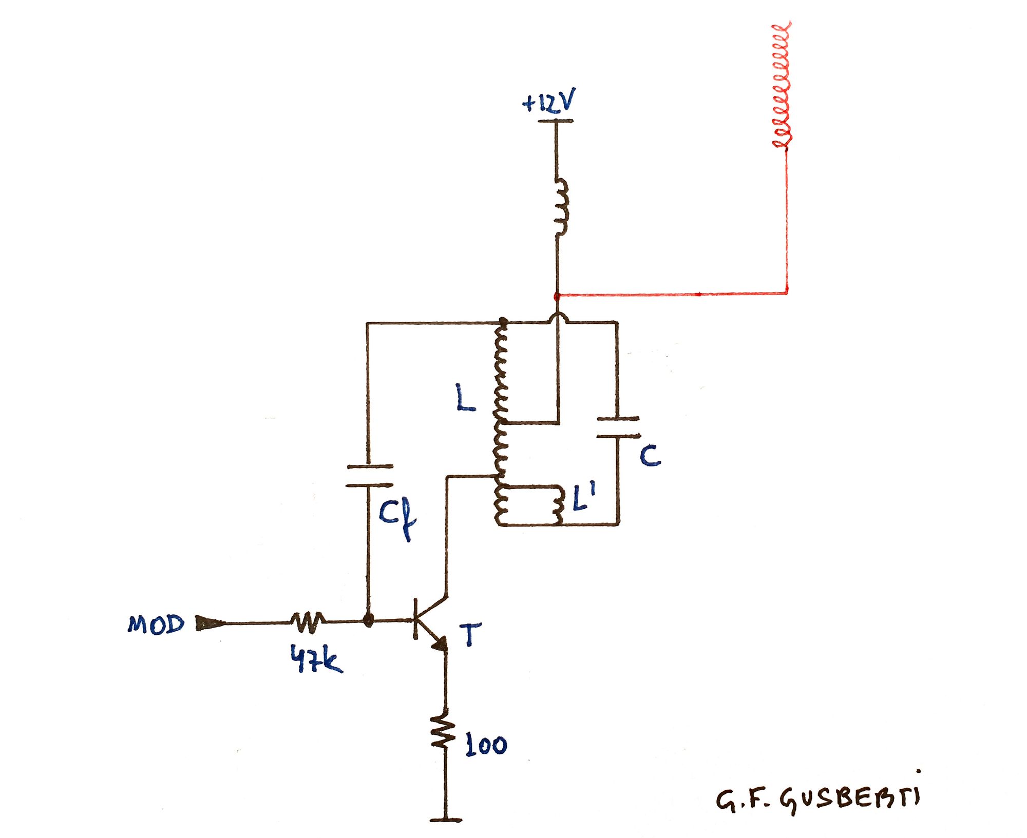
The DC feed inductor also works as the ground path for the feedback current, forming a detuned series tank with Cf. Looking at the color code, the inductance of ~150 nH matches a resonance frequency of ~250 MHz. An exact tuning of this feedback would lead the oscillator to mode jumping.
An interesting idea is seen here: the tank has a printed structure with different tap points, along the inductance L' (made with a thinner trace). This is used for setting the operational frequency of the remote, as the same hardware is used for 300 MHz, 310 MHz and 315 MHz.
The L' trace adds a short parallel path of current from the tank capacitor. This parallel path inductance reduces the total inductance of the tank L at that segment, increasing the resonance frequency.
Helix Antenna
The antenna is a common resonant monopole, constructed as a helix, to reduce the physical size. The first trial was made tuning the antenna with a VNA, implying a good match at 50 ohms. This leaded to a not working oscillator - the negative impedance created by the arrangement was not enough for overcoming the new load created by the antenna.
The end part of the helix was cut, detuning the antenna (from the perspective of a 50 ohm system), creating the correct opportunity for oscillator startup.
Simulation
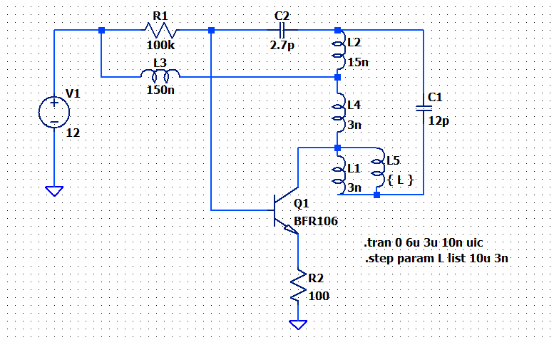
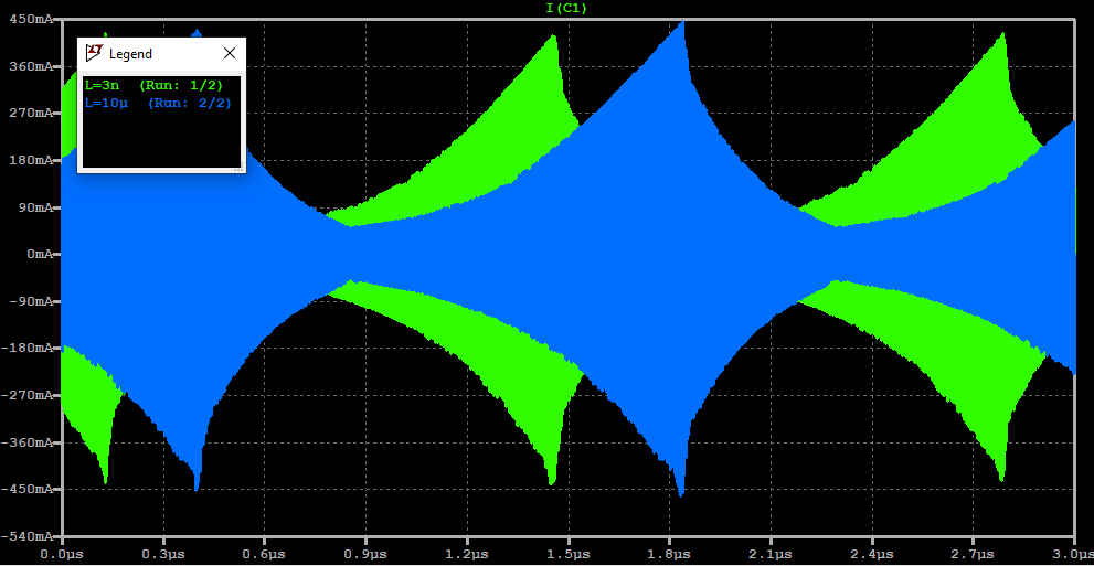
A LTSpice simulation indicates that the assumptions about the oscillator working principle are correct. The L5 inductor behaves as the taped tuning inductance L', demonstrating the operation at a higher frequency when it is connected.
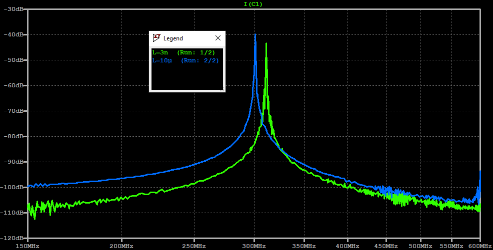
Mode jumping is observed if the L3 (DC feed inductor) is made exactly resonant at the frequency of operation.
Conclusion
Another concern was the high replacement of batteries, indicating a poor RF efficiency. A complete redesign of the circuit was not the intention of the writer, so other measures were taken.
An electrolytic capacitor was added, parallel to the battery, with the intention of reducing the effects of increasing internal resistance at the end of battery life. This energy storage also may help the oscillator startup.
The LED series resistor was modified, reducing the overall current consumption, further extending the battery life.
The end result was a 5x higher control range, with the hope of reducing the high battery replacement need.