
Written by a human, may contain mistakes.
I'm Gregory Frizon Gusberti; usually people call me Greg, and I was born in 1995. I'm a software/firmware developer and a radio-frequency engineer in my spare time.
This blog is my personal diary, where I document ideas, prototypes, and test results from experiments at my home lab.
I have developed several commercial solutions using C/C++, electronics, and high-level languages like JavaScript and Python. This document contains some curiosities about the projects!
I have a wide range of interests, many explored as hobbies, like in RF, analog electronics, and microwaves. Many of my designs are based on old techniques used in old state-of-the-art measurement equipment from HP and Tektronix.
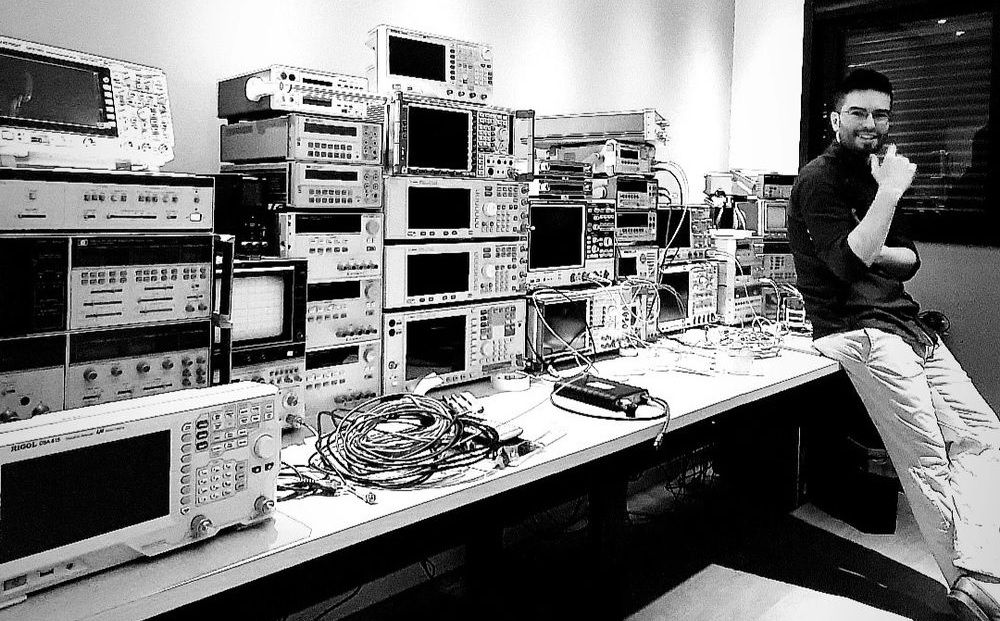
For a long time, having a lab, I bought and fixed a lot of high-end test equipment that allows me to design and characterize high-frequency stuff at home. Several of my projects I show on my YouTube channel, All Electronics.
Education
I hold a degree in electrical engineering from PUCRS (Pontifícia Universidade Católica do Rio Grande do Sul), where I graduated in 2016. During my studies, I worked at the Telecommunications Laboratory, gaining hands-on experience in digital communication systems.
I chose a specialization in digital telecommunications, which provided a strong foundation for understanding and developing real-time systems. Most of my coursework projects involved low-level programming languages such as Assembly, C, and VHDL.
Experience
Software and electronics have been my hobby since I was a kid. Here I tried to compile some of my professional experiences. My RF adventures are better described in the blog's articles and in the videos on the channel.
2022–Present: Firmware Engineer, Olibra (Bond Home, NJ, USA)
I currently stand as a director of engineering at Olibra, the company behind Bond: bondhome.io, and began there as an embedded engineer (firmware + hardware) and grew to have my own small division.
Olibra makes smart-home solutions, from a main RF hub device (Bond Bridge) to sensors and remotes. Currently, I'm working to develop a Smart By Bond technology for motorized shades, screens, and louvers.
The Smart By Bond solution consists of embedding firmware inside third-party motors - using a compatible chipset - and bringing telecommunication techniques to improve user experience.
For example, we are using concepts like TDM and forward error correction to allow the control and 2-way communication. Thus, making it possible to increase the number of shades and extend the range of typical installations.
2015–2022: Engineer → Senior Manager, D2G Tecnologia
I entered D2G Tecnologia, a small company in my city that developed several solutions for the publicity and audiovisual market. Most of the projects I show further in the page I developed there.
Since the company was in its beginnings, I was assigned the full stack for many of the projects: electronics, firmware, software, and web interfaces. That was my first experience with the integration of different systems for full commercial use.
The company grew rapidly, and I grew with it, becoming a senior manager and attending big players like Chevrolet, Samsung, Itaú, and Johnnie Walker. The majority of the projects were machines and robotics for TV commercials and promotional events.
Many of the projects required combining embedded hardware, real-time control, and user-facing interfaces, a multidisciplinary approach I continue to pursue in personal experiments.
2014–2015: Researcher, Telecommunications Lab, PUCRS
I worked as a researcher at my university's telecommunication laboratory. There we developed a DTV system using the ISDB-Tb standard. I worked on the algorithms for the real-time DPS of the transmitter.
DPS means digital pre-distortion and is a subsystem of the transmitter. It pre-distorts the signal before the power amplifier to cancel the distortion introduced by the non-linearities of the PA.
One branch of my research was to apply MLP neuron networks to model the PA non-linear response and gradient descent to learn the transfer function in real time.
2008–2009: Team Leader, Robotics Team, Colégio Marista Assunção
Leader of the robotics team of my school, Colégio Marista Assunção. There, we competed in the VEX/FIRST competitions. In 2008 we won the Brazilian championship, giving us the opportunity to compete in the VEX Robotics World Championship in 2009. I was 14 years old at that time.
These were astonishing times! I was a kid, and our school was not rich.. We had a limitation of 4 motors in the robot (because we had just those), while other rich teams had 8 or more. This forced us to be creative and smart, and we won with a smaller and more agile robot!
Projects
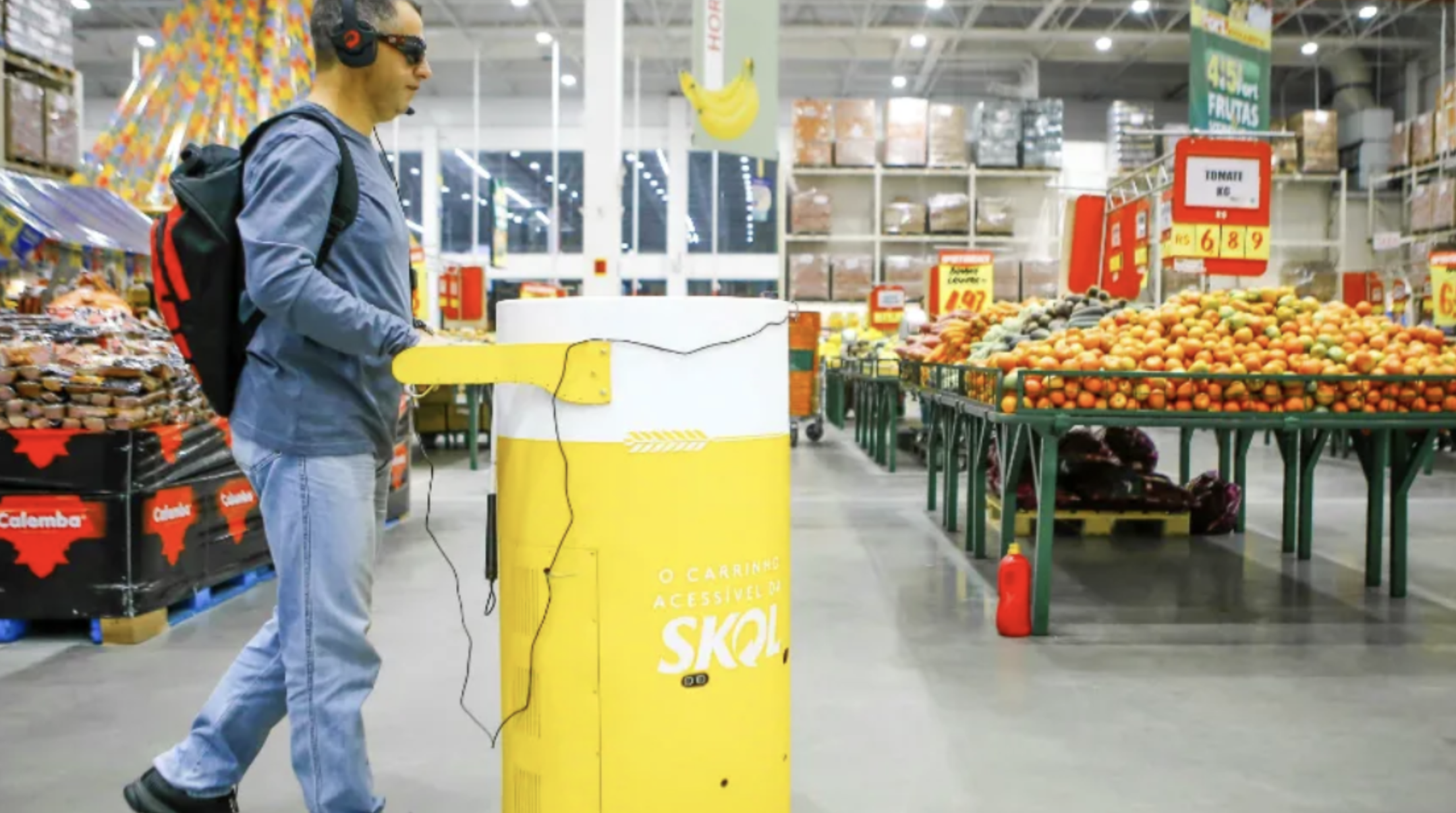
Self-Driving Shopping Cart for the Visually Impaired
This project was developed for Ambev, a big player in the beverage market in Brazil. They wanted to make a prototype self-driving shopping cart, allowing blind people to go to the supermarket without assistance. I developed this in the year 2018, and the cart ran experimentally in early 2019.
The challenge was to embed multiple subsystems in the cart and make it work reliably and safely for use by a blind person. I challenged myself to make the full robotics and navigation stack from scratch; it was pure fun, and I learned a lot!
It is difficult to describe the project in full detail, but I will glance over aspects I believe are interesting.
The architecture consisted of multiple Arduino Nano boards, programmed in raw C, and a central mini-Dell i3 computer running the robotics stack that I developed in JavaScript (NodeJS). All Arduino boards were connected to the main PC using a USB hub.
Frame: For the prototype, the structure of the cart was made of aluminum extruded parts and plywood. The frame was a stack of 3 floors, each one containing one of the subsystems: motor assembly, power, and sensors + inteligence.
Mechanics: I chose to use stepper motors, as I believed I would be able to do a good-enough open-loop estimation of the robot's position (dead reckoning) by counting pulses.
This indeed was true, and the real-time motion engine used the open-loop state of the robot. An ATmega MCU controlled both motors, and a fail-safe mechanism was in place, disabling motion if the USB data link was lost.
Sensors: The robot had 5 LIDARs and 4 ultrasonic range sensors. A single ATmega ran all data acquisition. All the data was fused in the JavaScript stack by using an occupancy grid and two different likelihood transfer functions for each type of sensor.
Basically, the occupancy grid integrates the readings into a 2D map, using cone-like likelihood functions. This means that each sensor projected an occupancy cone geometry over the grid, each cone starting from the estimated position of the robot.
As the robot moved, the grid was marked as white for free regions, black for obstacles, and gray for uncertain regions. This grid was used by the local motion planning algorithm.
State Estimation: For navigation in the 2D space of the supermarket, the robot required the estimation of its current position and heading angle.
The robot had a webcam pointing up, which detected QR codes installed in the ceiling. This was used to reset the state estimator every time a new QR was seen. Actually, the reset was not made in a single step and required multiple QR code readings, adjusting the state belief gradually (much like a Kalman filter).
In real-time, the state was updated by the pulse counting provided by the motor controller ATmega. Counts were transformed to the reference frame of the robot by a hard-coded geometrical model of the cart + wheels.
Motion Planning - Global: Global motion planning was provided by an A* algorithm that ran over a mesh of nodes created based on the floor plan of the supermarket. The list of items to purchase was transformed into 2D positions in the floor plan, which were mapped to A* mesh nodes.
This algorithm generated a global path for the robot to execute, assuming no dynamic obstacles would be present. The ideal trajectory was then forwarded to the local planning algorithm.
Motion Planning - Local: Local planning had the task of executing the global ideal path in the real world.
A pure-pursuit algorithm was used to select the next local target of the robot. A local target is the next position the robot should head to, thinking in a short time frame. This position started at the start of the global trajectory and was updated to follow the global trajectory as the robot approached it, always being ahead.
To reach the local target position, I made an algorithm based on DWA (Dynamic Window Approach). It computed the best motion state (linear speed + angular speed) that would reach the target position while being inside a window of allowed motion states.
The window, in this case, was set up to condition the motion to the physical limits of the robot (maximum acceleration and speed). States that would make the robot touch an occupied cell in the occupancy grid were discarded. Each state in the search window was extrapolated 5 seconds ahead, and the best state found was applied to the motors. This loop was executed 50 times per second.
Touch Bar: The handle of the cart was a metallic tube, isolated from the touch. By measuring its capacitance, the cart detected when the person was holding it. That was used to start and stop the movement of the robot from one purchase item to the next.
Power: Power was provided by two 12V-18Ah lead-acid batteries and a main PCB with charging and power-delivering electronics. The mini-PC ran with 19V, motors with 24V straight from the batteries, and the rest of the subsystems with 5V.
Safe Distance Alert
This was developed for a car insurance company, and the challenge was the development of a real-time image detection system that ran on a mobile browser as a web app. I developed this in 2016, when embedding real-time applications in mobile pages was not common.
The end goal was to help the user to keep a safe distance from the front vehicle and alarm in the event a possible collision could happen.
The first step was to capture hundreds of hours of rearview videos, using different phones positioned as they would be used in the final application. I remember driving in the city with phones attached to my car, deeply thinking about how the detection would be implemented.
That was late 2015, early 2016, when web mobile development was baby-stepping. I had recently read about WebWorkers - the way to multithread stuff in browsers - and had a feeling that, if the detection pipeline was fast enough, I could spawn multiple parallel detectors, distributing the video frames in round robin.
I first tried to implement a very light convolutional neural network, but that did not work well in real time; however, by later putting in more work, that code was used in other projects I developed in the company.
Looking at OpenCV solutions, I discovered the Haar Cascades using the Viola Jones method. The solution I found was to test the idea using OpenCV in C, which was helpful as I could use the already implemented scripts for training the detector.
The JavaScript detector had to calculate the Haar features for each frame and for different scales (pyramid processing), running the sequence of cascaded classifications for each search bounding box. The searching bounding box was swept over the frame by jumping far more than 1 pixel; this allowed the thing to run in real-time.
Ah, I was almost missing the fun of having my friends help to manually classify thousands of video frames! The task was easy - to draw rectangles over every vehicle - but so tedious!
It worked well enough! As is common to the method, some false positives were detected. However, with some averaging and thresholding of the bounding boxes over 3 to 5 frames, it worked pretty well!
Back to the mobile, I then implemented a JavaScript detector that was able to load the OpenCV file. The file contained the sequence of Haar features and the cascaded decision tree to be run. The premise of using the WebWorkers did not work so well, because the phones of that time, when running my detector, could keep 2 or 3 threads without heating too much or halting the browser.
To wrap up the project, the GUI was designed in HTML and CSS, based on feedback from the client. It was remarkable to see, with Google Analytics, the web page system being used by real customers!
DRSSTC Tesla Coils
The Tesla coil journey started when I was ~14 years old. I remember surfing the web and hitting YouTube videos of these spectacular machines. I immediately began to study how they work and decided I would try to make one.
This process took me years, and was an amazing course in high-power electronics. After 2 our 3 years of every day work after arriving from school, I finaly had the coil shown in the video below!
DRSSTC means Double Resonant Solid State Tesla Coil, and it is a special kind of electronic coil. When Nikola Tesla developed the coils, solid-state electronics haven't not being invented yet, and he used big capacitor banks and spark-gaps.
The electronic coil basically replaces the spark-gap for a high-power inverter, in my case a hige H-bridge, and the capacitor bank is made resonant with the primary coil.
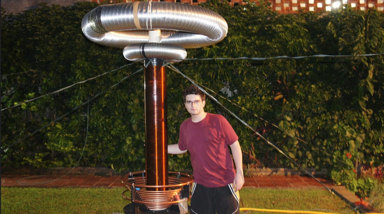
A secondary coil (the long tube) is made resonant close to the primary's frequency, using the top-load (the aluminum toroid) as the capacitive element. Energy is taken from a 650V DC link, converted to ~40kHz AC, and pushed though the double resonant circuit.
The resonant circuit actually works as an impedance matching network. Low impedance energy enters the primary coil, and is converted to high impedace at the top-load (toroid).
This process allows power to be delivered to the air, breaking its dielectric limit. The inverter run in burst mode, running 5 to 7 45kHz cycles 120 times per second (the 120Hz burst frequency is the noise you hear).
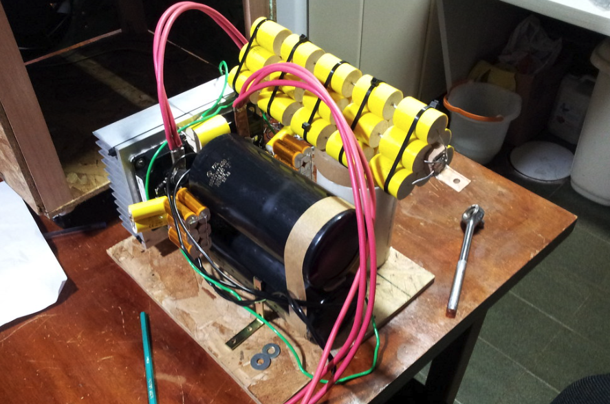
Burst mode is necessary because of the imense amout of power envolved. Every burst peaks ~1500A at the primary. This required huge IGBT transistors, DC bus capacitors, and special polypropilene capacitors for the primary's LC tank.
The DC link was generated by a quad-phase PFC boost converted that I developed after I had the coil working. Using four interleaved phases allowed the usage of slower devices, while providing good regulation and easier filtering at the input.